
Apparatus and method for automatically converting thermal displacement compensation parameters of machine tool

A technology of compensating parameters and automatic conversion, applied in automatic control devices, feeding devices, computer control, etc., can solve the problems of decreased production efficiency, neglect, and decreased processing accuracy.

Active Publication Date: 2018-12-21
DN SOLUTIONS CO LTD
View PDF6 Cites 9 Cited by
  • Summary
  • Abstract
  • Description
  • Claims
  • Application Information

AI Technical Summary

Problems solved by technology

[0012] That is, the thermal deformation error compensation device of the conventional machine tool does not consider the characteristics of the thermal displacement error caused by the temperature change between the equipment models (equipment types), and applies the fixed thermal displacement compensation parameters extracted from the representative models. The thermal displacement compensation amount calculation formula calculates the thermal displacement compensation amount to calculate the thermal displacement compensation amount, so there is a problem that it is impossible to perform accurate thermal displacement error compensation for each equipment model, resulting in a decrease in processing accuracy
[0013] In addition, even in the same equipment, in order to calculate a new fixed thermal displacement compensation parameter according to the period of use or the state of use, it is necessary to stop the machine tool and recalculate it, so there is a problem of lowering productivity

Method used


Image

  • Apparatus and method for automatically converting thermal displacement compensation parameters of machine tool
  • Apparatus and method for automatically converting thermal displacement compensation parameters of machine tool
  • Apparatus and method for automatically converting thermal displacement compensation parameters of machine tool

Examples


Embodiment Construction

[0057] Preferred embodiments of the present invention will be described in detail below with reference to the accompanying drawings.

[0058] Unless there is a special definition, all terms in this specification have the same common meanings as understood by those skilled in the art. When a term used in this specification conflicts with the usual meaning of the term, follow the Definition.

[0059] It should be noted that the inventions to be described below are only used to illustrate the embodiments of the present invention and are not intended to limit the scope of rights of the present invention. The same reference numerals used throughout the specification represent the same constituent elements.

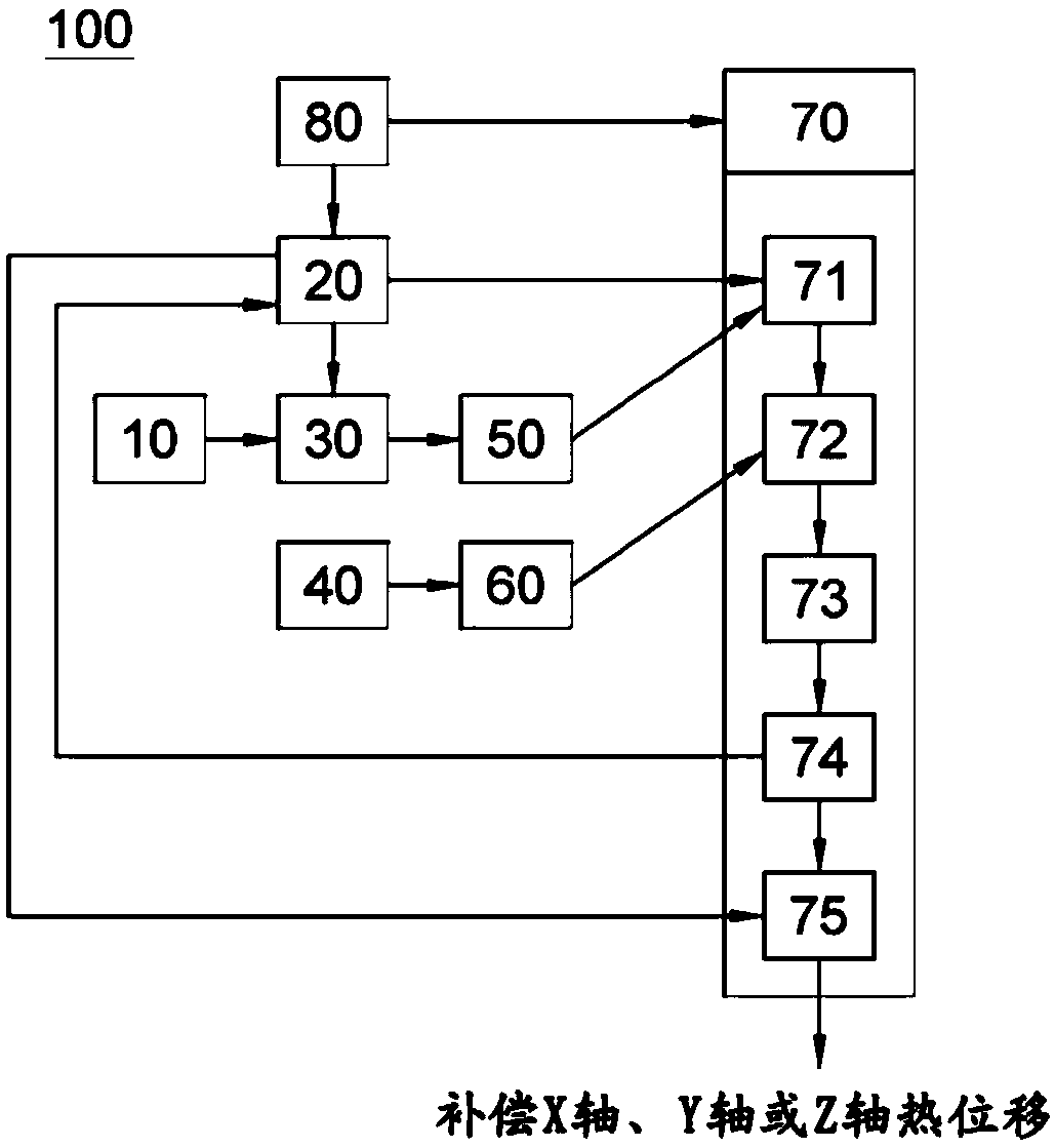
[0060] image 3 It is a block diagram of the thermal displacement compensation parameter automatic conversion device of the machine tool of the embodiment of the present invention, Figure 4 It is a diagram illustrating a screen of an operation panel for calculating compensat...


PUM


Abstract

The present invention relates to an apparatus and a method for automatically converting thermal displacement compensation parameters of a machine tool, wherein, according to operation states of a machine tool or various types of machine tools, compensation parameters of a thermal displacement compensation equation for a machine tool are automatically converted in real time such that the same can be optimized for a current thermal displacement status of the machine tool, on the basis of thermal displacement data of the machine tool, calculated by measuring z-direction or y-direction displacement data of the tool end of a reference tool, measured by a tool measurement unit, or the processed portion of a machined material, and temperature data measured by a temperature measurement unit. Therefore, the present invention can improve the machining accuracy of a machine tool by minimizing machining errors due to thermal displacement.

Description

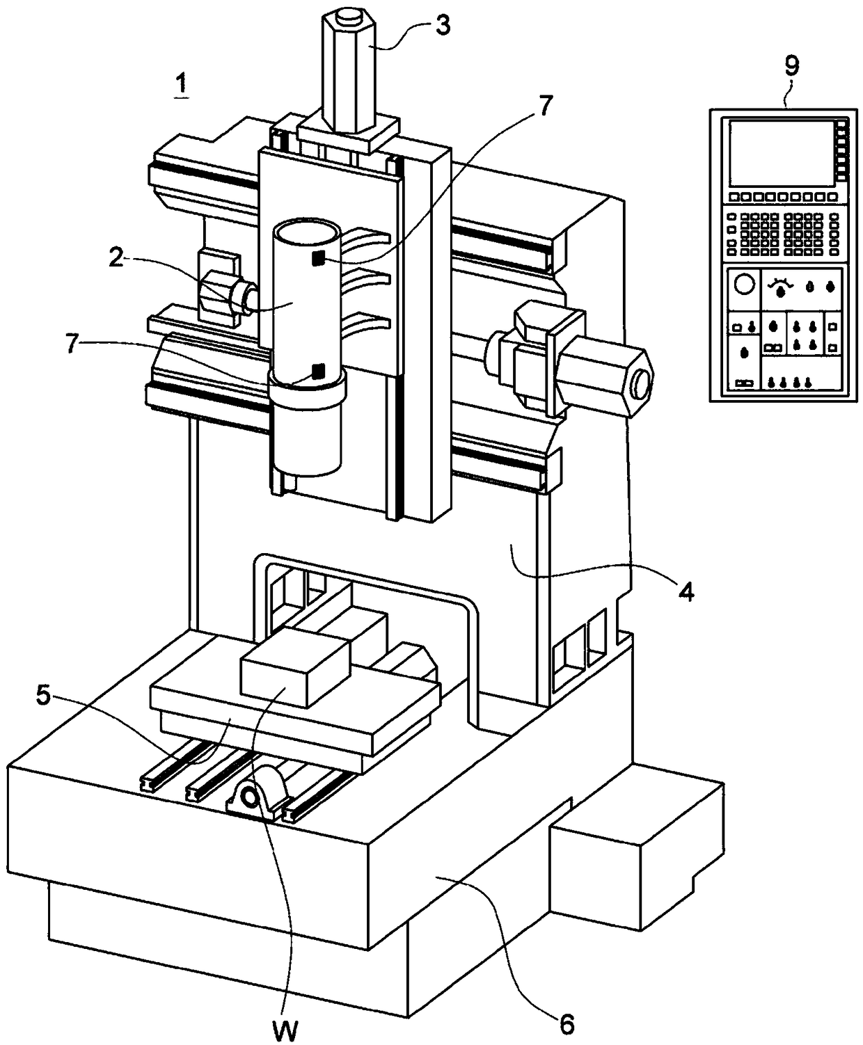
technical field [0001] The present invention relates to a kind of thermal displacement data of a machine tool that can be calculated by measuring the displacement data of the Z direction or the Y direction of the tool tip of the reference tool measured by the tool measuring unit or measuring the processed part of the material being processed and measured by the temperature measuring unit The thermal displacement compensation parameter automatic conversion device and conversion method of the machine tool can be automatically converted in real time by the temperature data of the machine tool to improve the machining accuracy. Background technique [0002] Various types of machine tools such as turning centers, machining centers, portal machining centers, switch turns, electrical discharge machines, horizontal NC drilling machines, and CNC lathes are widely used in various industrial sites according to the purpose of the corresponding work. [0003] Such as figure 1 As shown i...

Claims


Application Information

Patent Timeline
Patent Type & Authority Applications(China)
IPC IPC(8): B23Q11/00B23Q15/18B23Q17/09G05B19/404
CPCB23Q11/00B23Q17/09G05B19/404G05B2219/49206G05B2219/49207G05B2219/49209B23Q11/0003B23Q11/0007B23Q15/18B23Q17/0904B23Q23/00G05B2219/49219G06F17/16
Inventor 金基洪
Owner DN SOLUTIONS CO LTD
Learn More