Injection arrangement for injecting water and fuel

A component and fuel technology, applied in the direction of low pressure fuel injection, low pressure fuel injection, fuel injection device, etc., can solve problems such as reducing installation space, and achieve the effect of reducing fuel consumption and reducing knocking tendency

Inactive Publication Date: 2018-12-21
ROBERT BOSCH GMBH
View PDF7 Cites 0 Cited by
  • Summary
  • Abstract
  • Description
  • Claims
  • Application Information

AI Technical Summary

Problems solved by technology

However, especially due to the ever-decreasing installation space of internal combustion engines, problems with the arrangement of the injection valves gradually arise here.

Method used


Image

  • Injection arrangement for injecting water and fuel
  • Injection arrangement for injecting water and fuel

Examples


Embodiment Construction

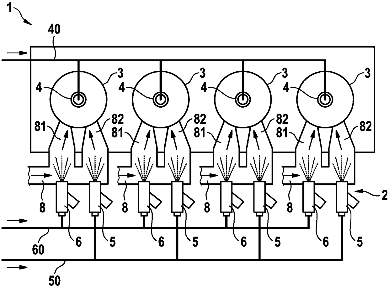
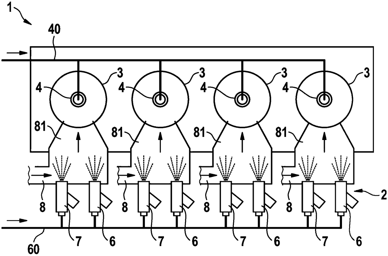
[0016] Refer below figure 1 The jetting assembly 1 according to the first preferred embodiment of the present invention is explained in detail.

[0017] as from figure 1 As can be seen in the figure, the injection system 2 is arranged in an internal combustion engine 1 having four cylinders 3 .

[0018] In this case, exactly three injection valves are provided per cylinder 3 , so that the injection system 2 has a total of twelve injection valves.

[0019] as from figure 1 It can be seen that each cylinder 3 has a first fuel injection valve 4 arranged directly thereon for direct injection. The high-pressure feed line 40 supplies the four fuel injection valves 4 with fuel under high pressure.

[0020] A first intake duct 81 and a second intake duct 82 for each cylinder 3 are arranged on the intake region 8 of the internal combustion engine. Two intake passages 81, 82 respectively connect an intake pipe or the like to the cylinder, wherein the connection between the intake p...


PUM


Abstract

The invention relates to an injection arrangement of an internal combustion engine, comprising at least one cylinder (3), a first fuel injection valve (4) for the injection of fuel, a second water injection valve (6) for the injection of water and a third injection valve (5; 7) for injecting a fluid, wherein the first, second and third injection valves are associated with exactly one cylinder (3)of the internal combustion engine.

Description

technical field [0001] The invention relates to an injection assembly for injecting water and fuel of an internal combustion engine and to an internal combustion engine having such an injection assembly. Background technique [0002] Today, there are continuous attempts to reduce consumption and emissions in internal combustion engines. For this purpose, in particular the compression ratio is increased and the concept of miniaturization in relation to the supercharging of the internal combustion engine is also gradually implemented. At operating points with high loads, however, such internal combustion engines cannot be operated at an optimal operating point, since the tendency to knock and the high exhaust gas temperature set a limit here. One measure, in particular to reduce the tendency to knock and to lower the exhaust gas temperature, is the injection of water. However, in particular due to the ever-decreasing installation space of internal combustion engines, problem...

Claims


Application Information

Patent Timeline
Patent Type & Authority Applications(China)
IPC IPC(8): F02M43/00F02M61/14F02M69/04F02M25/022F02M25/03
CPCF02B17/005F02M25/028F02M43/00F02M61/145F02M69/045Y02T10/12
Inventor J·哈根洛赫I·布拉克P·申克
Owner ROBERT BOSCH GMBH
Why Eureka
Try Eureka