Check patentability & draft patents in minutes with Patsnap Eureka AI!

Optical coupling assembly

A technology for optical coupling and optical components, applied in the field of optical coupling components, which can solve problems such as preventing use, limiting or complicating, performance degradation, etc.

Active Publication Date: 2018-12-21
MOLEX INC
View PDF4 Cites 3 Cited by
  • Summary
  • Abstract
  • Description
  • Claims
  • Application Information

AI Technical Summary

Problems solved by technology

These fundamental properties limit or complicate the use of polymeric light components in many light applications
[0006] In some applications, the large dN / dT and CTE properties may produce variations in the location of the focused light leading to degradation of the optical connection properties with temperature
This attenuation of performance limits and sometimes prevents the use of polymer optics in many fiber optic applications
In some cases, the application of single-mode fiber may be extremely prone to performance degradation due to the influence of temperature changes

Method used


Image

  • Optical coupling assembly
  • Optical coupling assembly
  • Optical coupling assembly

Examples


Embodiment Construction

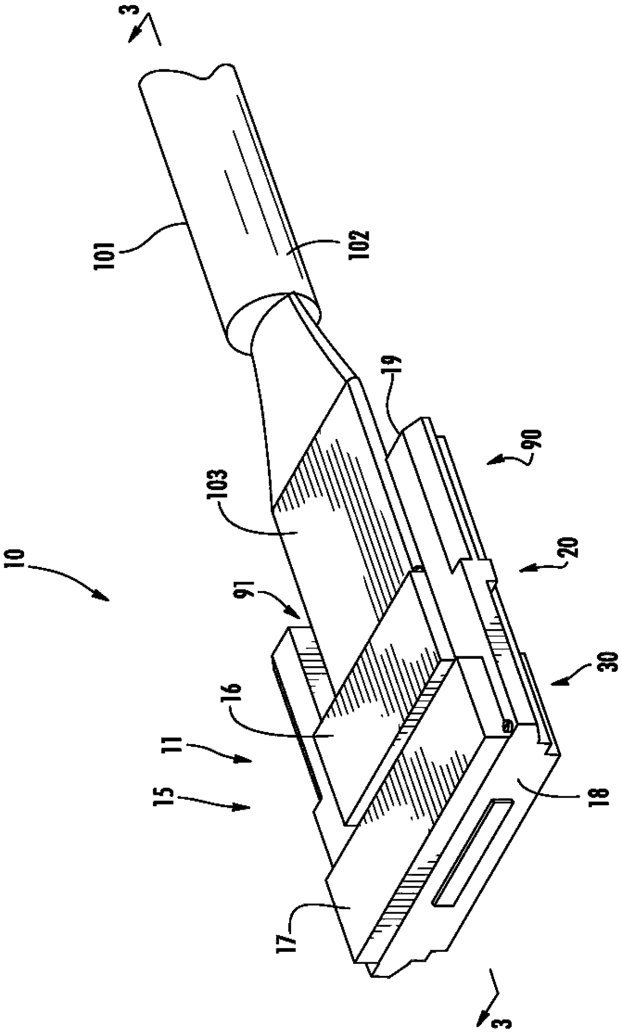
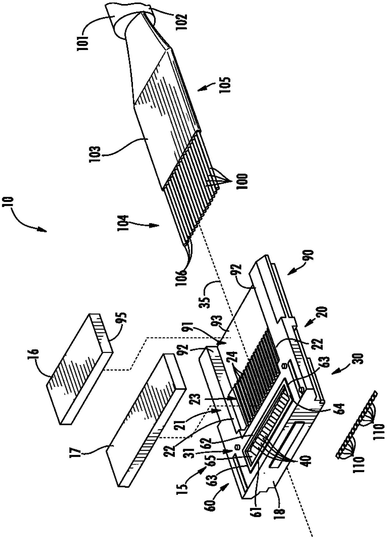
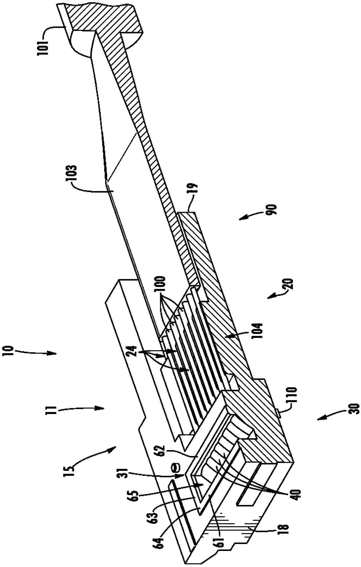
[0024] refer to Figure 1 to Figure 2 , an optical system 10 includes an optical component 11 (such as a transceiver) optically coupled or interconnected to a cable 101 of a plurality of optical fibers 100 such as glass, quartz or plastic ( figure 2 ) in the form of a first light element and a plurality of photoelectric elements 110 in the form of a second light element. Cable 101 may include any number and type of optical fibers 100 . For example, as shown, the cable 101 is generally circular and includes a plurality of optical fibers 100 in ribbon form extending from a jacket 102 of the cable. Material (not shown) surrounding the optical fiber 100 , such as a buffer body 103 , may be removed from the end 104 to facilitate precise positioning of the plurality of optical fibers within the optical assembly 11 . In an alternative embodiment not shown, the cable 101 may include a plurality of loose optical fibers 100 . Optical fiber 100 may be of any construction or may be of...


PUM

PropertyMeasurementUnit
refractive indexaaaaaaaaaa

Abstract

An optical system includes a base with a fiber retention and alignment section having at least one alignment member. An optical coupling section of the base has an optical coupling block and includesat least one optical coupling element with an ellipsoidal reflecting surface defining first and second focal points. First and second focal surface are generally aligned with the first and second focal points, respectively. An optical path extends through each optical coupling element and is aligned with one of the alignment members. An optical fiber is positioned within each alignment member adjacent a first focal surface and an optical component is optically aligned with each optical fiber and positioned adjacent one of the second focal surfaces.

Description

[0001] Cross References to Related Applications [0002] This application asserts U.S. Provisional Patent Application No. US62 / 303933, filed March 4, 2016, entitled "Optical Coupling Assemblies," and U.S. Provisional Patent Application, filed November 9, 2016, entitled "Optical Coupling Assemblies" No. US62 / 419752, the entire contents of which are hereby incorporated by reference in their entirety. technical field [0003] The present invention relates generally to optical components, and more particularly to an optical coupling component and an optical coupling assembly for interconnecting optical components. Background technique [0004] Optical modules are typically configured for transmitting multimode signals in short reach applications such as servers, data storage, and data management. Optical modules can also be configured for transmission of single-mode fiber optic signals in medium reach applications such as remote control antennas and data centers. Optical modul...

Claims


Application Information

Patent Timeline
Patent Type & Authority Applications(China)
IPC IPC(8): G02B6/42
CPCG02B6/262G02B6/3652G02B6/4214G02B6/4225G02B6/425G02B6/4292G02B6/3636G02B6/3644
Inventor 罗杰·科曼斯D·古肯伯格马克·哈里森拉塞尔·斯蒂尔斯
Owner MOLEX INC
Features
  • R&D
  • Intellectual Property
  • Life Sciences
  • Materials
  • Tech Scout
  • Unparalleled Data Quality
  • Higher Quality Content
  • 60% Fewer Hallucinations
Learn More