Device and method for classification of tissue

a tissue and device technology, applied in the field of tissue classification devices and methods, can solve the problems of large proportion of errors in medicine, high cost, and high cost, and achieve the effects of improving data, enhancing the value of a measurement, and improving data

Inactive Publication Date: 2003-07-15
J FITNESS LLC
View PDF64 Cites 140 Cited by
  • Summary
  • Abstract
  • Description
  • Claims
  • Application Information

AI Technical Summary

Benefits of technology

Another object is that this data can be enhanced by collection over time. In many medical applications, the value of a measurement is enhanced by determination of temporal characteristics. For example, the detection of an enlarging bleed in head tissue holds a different significance than the detection of a stable, but otherwise similar, bleed. In underwater applications, the ability to detect moving nearby objects may also be important. Subtraction of the data at one point in time from data collected at a second point in time allows elimination of many types of individual tissue variations, and can yield improved data.

Problems solved by technology

A major portion of time spent in medicine is directed toward the problem of diagnosis, and a large proportion of the errors in medicine are made here.
A delayed diagnosis raises the level of pain and suffering, and may allow progression to the point of irreversibility; an incorrect diagnosis can be even worse, leading to treatment that is at best unnecessary and at worst harmful or fatal.
Each of these does not perform a tissue analysis, requires fluid or tissue removal or sampling, utilizes fluorescence or other emission-based techniques which measure light other than that used to perform the illumination, is restricted to external or penetrating use, or does not teach tissue classification or identification.
Automated classification of tissues for general clinical use via light in vivo has not been taught, nor has such a tool been successfully commercialized.

Method used


Image

  • Device and method for classification of tissue
  • Device and method for classification of tissue
  • Device and method for classification of tissue

Examples


example 1

Classification of Tissues By Type

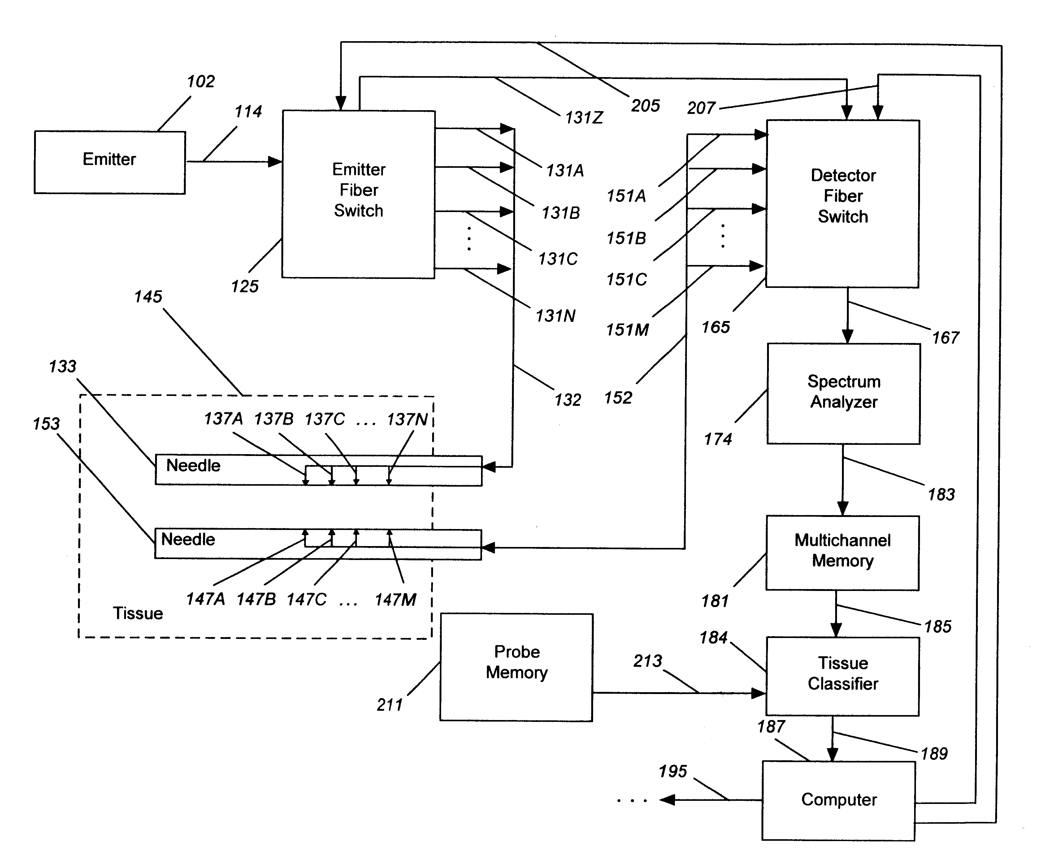
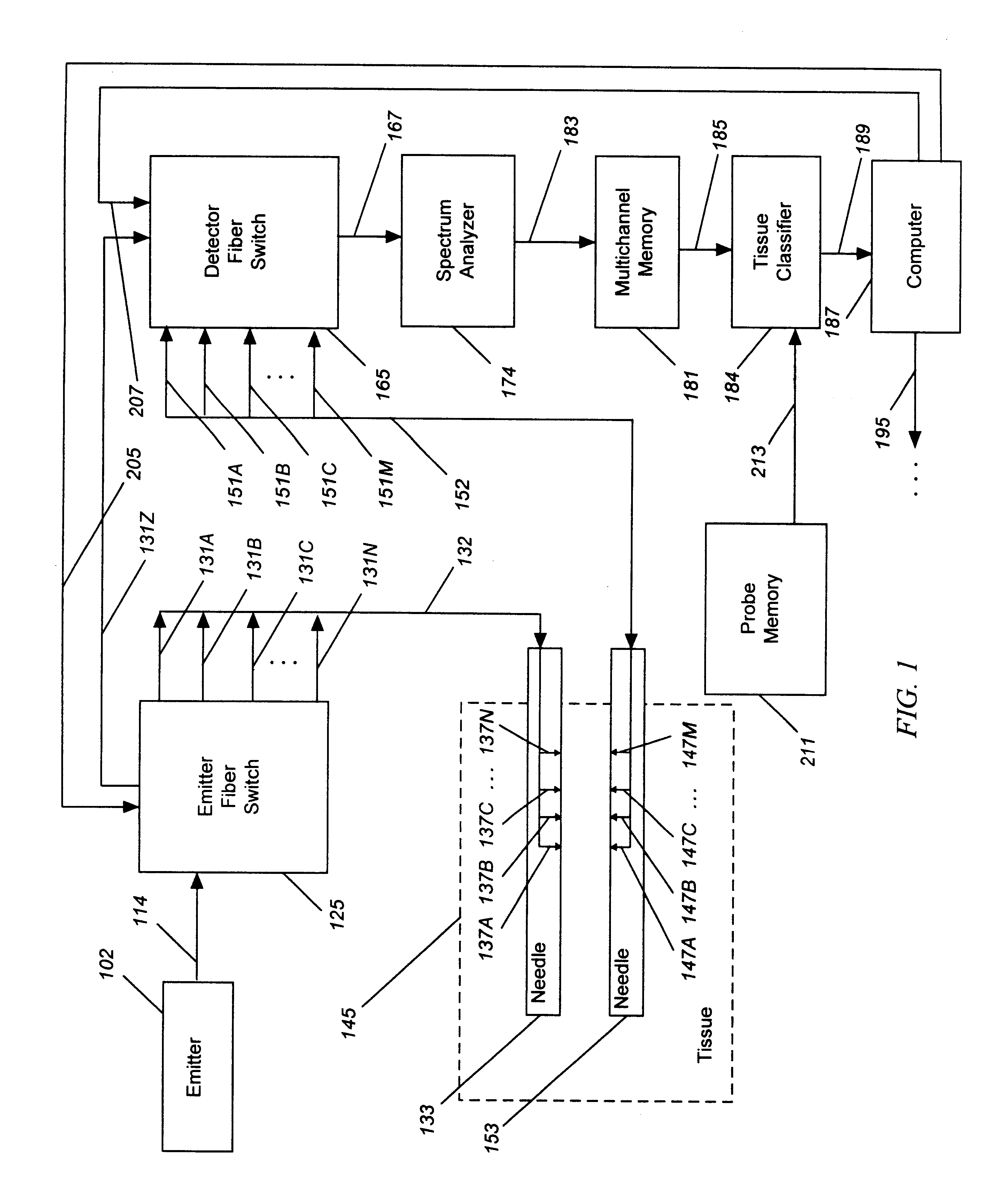
Tissue classification can be used to recognize different tissue types. In this experiment, different tissues were measured using the device similar to that shown in FIG. 1, and light was collected from one emitter and detector pair. Optical spectra from muscle and fat are shown in FIG. 5. There are distinct differences in spectra between each tissue shown, for example between muscle 512 and fat 514. These differences allow for a simple discrimination between the tissue types, and several algorithms can be selected to classify the tissue. In this case, the algorithm could be as simple as:

a) if the absorbance peaks at a wavelength over 575 nm, then tissue is fat; or,

b) otherwise, the tissue is not fat.

This method requires use of the entire collected spectrum in order to identity a peak wavelength. The classification is performed by a computer-based classifier, such as classifier 184 in FIG. 1. A more complex algorithm could use the ratio of absorbance ...

example 2

Classification of Tissue Types as an Image

Optical methods can be used to perform imaging (Benaron, U.S. Pat. No. 5,413,098). Tissue classification criteria, taught in the present invention, can then be applied to such images. In this example, image classification has been used to process an optical image of tissue, and then to classify for the presence of a bleed in the brain, or hemorrhage, in the brain of an infant.

To generate this image, we optically monitored the head of a living infant at risk for bleeding using the device shown in FIG. 1 attached using optical headband 352 wrapped around head 362, shown schematically in FIG. 2E and photographically in FIG. 6. Note that in FIG. 6, the infant is receiving heart / lung bypass, so that the oxygenation of the blood leaving the brain can be directly measured by sampling blood from bypass tube 518. Optical image 526 in FIG. 7 was tomographically generated from the optical data collected using the method and device of U.S. Pat. No. 5,41...

example 3

Classification for Detection of Changes in Tissue State

In this example, a change in the state of the tissue is monitored. Freezing, a change of tissue state, can be detected using changes in the optical characteristics of the tissue.

The detection of freezing in a turbid liquid may be important in the monitoring of materials which must be frozen, such as with biologic samples. It may also be important to be able to detect when freezing has been completed, such as use of an optical device to verify that poultry has been filly frozen, in order to minimize time of freezing before removal from a freezing bath, or that human tissue has been adequately frozen during a procedure known as cryosurgery. In cryosurgery, treatment of a cancer or other lesion is achieved by freezing the tumor using a liquid nitrogen filled needle stuck into the tumor. This allows killing of the tumor without having to cutup tissue in order to remove it. This is important if the tumor is in an critical location in...


PUM

PropertyMeasurementUnit
wavelengthsaaaaaaaaaa

Abstract

A diagnostic monitor for classifying biological tissue in which a light emitter (102) is optically coupled to the tissue to be diagnosed (145) and a light detector (174) is optically coupled to the tissue to detect a portion of the light which passes through the tissue. The tissue classifier (184) receives a signal from the detector and provides an optical classification output signal (195), wherein the tissue is classified by type or state, either for detection, localization, or imaging. A method of classifying tissue is also described.

Description

The present invention relates to a device and method for detecting, localizing, and imaging in a radiation-scattering medium, and more particularly relates to an optical device and method for measuring information regarding the interaction of emitted light with biological tissue during passage of light through the tissue, and using said information to classify the tissue by type or state, either for detection, localization, or imaging.A major portion of time spent in medicine is directed toward the problem of diagnosis, and a large proportion of the errors in medicine are made here. A delayed diagnosis raises the level of pain and suffering, and may allow progression to the point of irreversibility; an incorrect diagnosis can be even worse, leading to treatment that is at best unnecessary and at worst harmful or fatal.Medical imaging, while highly sophisticated, usually merely images body structure without classification into tissue type. For example, an X-ray shows light and dark a...

Claims


Application Information

Patent Timeline
Patent Type & Authority Patents(United States)
IPC IPC(8): A61B18/00A61B5/00G01N21/47A61B18/14A61B17/068A61B17/00
CPCA61B5/0059A61B5/14553A61B5/1459A61B5/415A61B5/418A61B5/6848A61B5/7264A61B18/00G01N21/4795A61B5/0073A61B5/0075A61B5/0084A61B17/068A61B18/14A61B2017/00022A61B2017/00123A61B2017/00508A61B2017/00557A61B2560/0276A61B2562/0242A61B2562/08A61B6/506A61B5/4076G16H50/20
Inventor BENARON, DAVID A.RUBINSKY, BORIS
Owner J FITNESS LLC
Why Eureka
Try Eureka