Resin sealing device
A resin sealing device and resin sealing technology, which are applied in electrical components, semiconductor/solid-state device manufacturing, circuits, etc., can solve the problems of different resin sealing thicknesses, high storage costs, and mold frame manufacturing costs, etc. The effect of improving work efficiency and improving accuracy
- Summary
- Abstract
- Description
- Claims
- Application Information
AI Technical Summary
Problems solved by technology
Method used
Image
Examples
Embodiment approach 1
[0105] (overview)
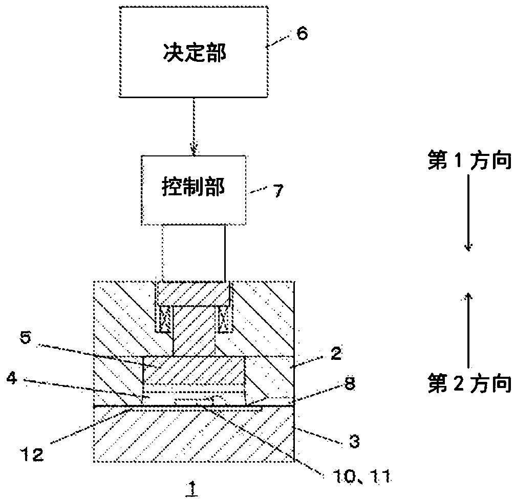
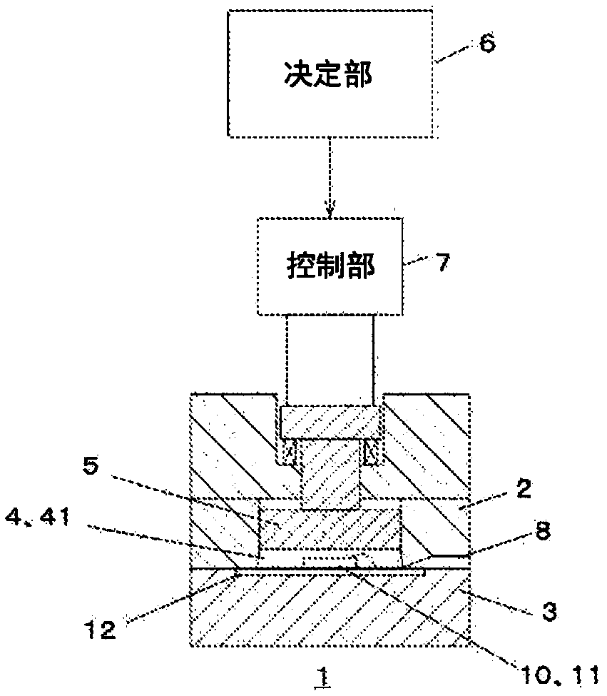
[0106] First, an overview of the resin sealing device according to Embodiment 1 will be described. figure 1 It is a front view of the resin sealing device according to Embodiment 1 of the present invention. figure 2 It is a front view of the resin sealing device according to Embodiment 1 of the present invention. figure 1 A state in which the movable cavity described later is in the initial position (position before movement), figure 2 A state in which the movable cavity is lowered according to the sealed space 4 is shown.
[0107] The resin sealing device 1 includes a first frame 2 , a second frame 3 , a sealed space 4 , a movable cavity 5 , a determination unit 6 , a control unit 7 , and a resin injection unit 8 . In addition, the resin sealing device 1 seals the object 10 to be sealed with resin. As an example of the sealing object 10, in figure 1 , figure 2 Among them, the member on which the semiconductor element 11 is mounted on the electr...
Embodiment approach 2
[0204] Next, Embodiment 2 will be described. In Embodiment 2, position correction of the movable cavity 5 will be described.
[0205] (Position correction of movable cavity)
[0206] As described in Embodiment 1, the movable cavity 5 returns to its original position (initial position) after moving to apply pressure to the resin. By returning the movable cavity 5 to the initial position, the resin sealing process can be continuously performed on the next object to be sealed 10 . For example, figure 2 A state in which the movable cavity 5 is moving downward is shown. figure 1 The state where the movable cavity 5 is in the initial position before moving downward is shown. Thus, in figure 1 state, also shows the figure 2 The movable cavity 5 is returned to the initial position after the pressurization by the downward movement is completed.
[0207] Here, there may be a case where the movable cavity 5 does not return to the initial position after pressurization, but stay...
Embodiment approach 3
[0218] Next, Embodiment 3 will be described. In Embodiment 3, a case where a resin sheet is used as the resin forming the resin sealing layer 41 will be described. In Embodiments 1 and 2, the resin is injected into the sealed space 4 from the resin injection port 8 . The resin sealing layer 41 is formed by pressurizing the movable cavity 5 with respect to the injected resin.
[0219] In the resin sealing device 1 according to Embodiment 3, the resin is not injected from the resin injection port 8 , but the resin sheet is placed on the object 10 to be sealed. The movable cavity 5 applies pressure to the set resin sheet to form the resin sealing layer 41 .
[0220] Figure 8 It is a front view of a resin sealing device according to Embodiment 3 of the present invention.
[0221] exist Figure 8 In the resin sealing device 1 described above, a resin sheet 40 is provided in the sealed space 4 . At this time, since the movable cavity 5 is configured to move from above to belo...
PUM
 Abstract
Description
Claims
Application Information
 - R&D
- Intellectual Property
- Life Sciences
- Materials
- Tech Scout
- Unparalleled Data Quality
- Higher Quality Content
- 60% Fewer Hallucinations
Browse by: Latest US Patents, China's latest patents, Technical Efficacy Thesaurus, Application Domain, Technology Topic, Popular Technical Reports.
© 2025 PatSnap. All rights reserved.Legal|Privacy policy|Modern Slavery Act Transparency Statement|Sitemap|About US| Contact US: help@patsnap.com


