Steel pipe end face polishing machine

A steel pipe and grinding machine technology, which is applied in the direction of grinding racks, grinding machine parts, grinding machines, etc., can solve the problems of high labor intensity for operators, unfavorable subsequent application of steel pipes, and low grinding precision of steel pipes, and achieve flexible setting positions , convenient positioning, and optimized performance

Pending Publication Date: 2018-12-25
浙江鑫桦钢管有限公司
View PDF6 Cites 9 Cited by
  • Summary
  • Abstract
  • Description
  • Claims
  • Application Information

AI Technical Summary

Problems solved by technology

[0003] In the prior art, the end face of the steel pipe is polished by manual grinding, that is to say, when the end face of the steel pipe is polished, the operator holds the grinder to grind the end face of the steel pipe. This operation mode causes the operator to have a large labor intensity. In addition, The manual grinding method results in low grinding precision of the steel pipe, which is not conducive to the subsequent application of the steel pipe
The grinding method of manual grinding is less efficient

Method used


Image

  • Steel pipe end face polishing machine
  • Steel pipe end face polishing machine
  • Steel pipe end face polishing machine

Examples


Embodiment 1

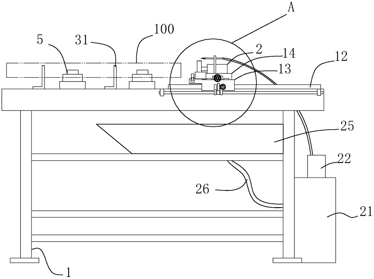
[0030] The steel pipe end face grinder is used for grinding the end face of the steel pipe 100 to facilitate the subsequent use of the steel pipe 100 .

[0031] like figure 1 , The steel pipe end face grinding machine includes a frame 1, which can be formed by splicing rods, and the rods can be spliced ​​by bolts or welded to form the frame 1.

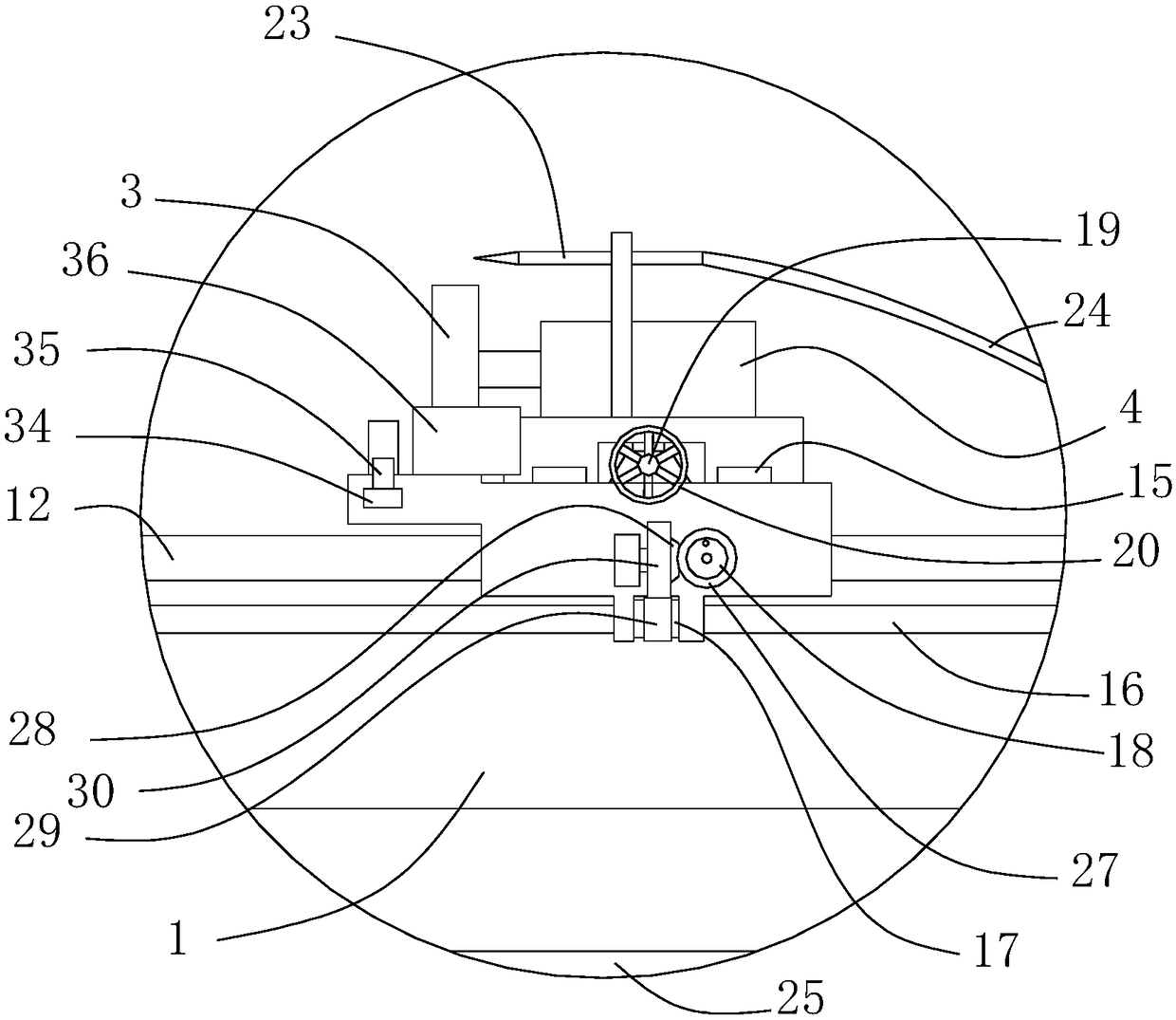
[0032] like figure 1 , figure 2 , the frame 1 is provided with a grinder 2, the grinder 2 includes a grinding head 3 and a driving motor 4 that drives the rotation of the grinding head 3, and the driving motor 4 is fixed on the frame 1, The driving motor 4 includes an output shaft, and the grinding head 3 is fixed on the output shaft of the driving motor 4 through threads. .

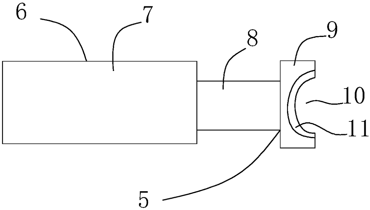
[0033] like figure 1 , figure 2 , image 3 , the frame 1 is also provided with a clamper 5 for clamping the steel pipe 100 , there are multiple clampers 5 , and the clampers 5 are respectively located on both sides of the steel pipe 100 to clamp the stee...

Embodiment 2

[0042] This embodiment is an optimization scheme for embodiment 1 in combination with embodiment 1.

[0043] like figure 1 , figure 2 , the steel pipe end face grinding machine also includes a cutting fluid supplier, the cutting fluid supplier includes a water tank 21, the water tank 21 is used to accommodate the cutting fluid, the water tank 21 can be fixed with the frame 1, or the water tank 21 can not be fixed with the frame 1 , the installation position of the water tank 21 is not specifically limited.

[0044] A water pump 22 is arranged in the water tank 21 , and a nozzle 23 is arranged on the sliding frame 14 , and the water pump 22 supplies liquid to the nozzle 23 through a hose 24 .

[0045] The cutting fluid supplier also includes a water collecting box 25 for collecting the cutting fluid ejected from the nozzle 23. The water collecting box 25 communicates with the water tank 21 through a pipeline 26. The water collecting box 25 is mainly used for collecting the c...

Embodiment 3

[0048] This implementation introduces the structure of the gear transmission mechanism in combination with Embodiment 1 or Embodiment 2.

[0049] like figure 1 , figure 2 , the handle 18 is rotatably connected to the sliding seat 13, the gear transmission mechanism includes a driving bevel gear 27 which rotates synchronously with the handle 18 and a driving bevel gear 27 which is rotatably connected to the sliding seat 13 and the driving bevel gear 27 Engaged driven bevel gear 28. The setting of the driving bevel gear 27 and the driven bevel gear 28 is mainly used to change the direction of power transmission, so that the setting position of the handle 18 is flexible, and the operability of the handle 18 is optimized.

[0050] The nut 17 is provided with a first tooth portion 29, the nut 17 and the first tooth portion 29 are integrally structured, and the driven bevel gear 28 is provided with a second tooth meshing with the first tooth portion 29. The part 30, the driven b...


PUM


Abstract

The invention relates to steel pipe processing equipment, in particular to a steel pipe end face polishing machine and belongs to the field of machining of steel pipes. The provided steel pipe end face polishing machine aims at achieving the technical purpose that the precision of polishing the end face of a steel pipe is improved. The steel pipe end face polishing machine comprises a rack, clamping devices and a polishing device are arranged on the rack, a transverse guide rail is further arranged on the rack and provided with a sliding base, a longitudinal guide rail is arranged on the sliding base and provided with a sliding frame, and the polishing device is fixed to the sliding frame. According to the scheme, compared with the prior art, the steel pipe end face polishing machine has the advantages that the clamping devices tightly clamp the steep pipe, the sliding base is moved, the sliding frame can make the polishing device conduct transverse and longitudinal movement with respect to the end face of the steel pipe, and thus the end face of the steel pipe can be polished conveniently; meanwhile, through arrangement of the sliding base and the sliding frame, the precision of polishing the end face of the steel pipe is high and is improved.

Description

technical field [0001] The invention relates to steel pipe processing equipment, in particular to a steel pipe end face grinder, and belongs to the field of steel pipe processing. Background technique [0002] The steel pipe is a hollow rod-shaped structure, which is widely used in the prior art, such as wiring, water supply, steam supply and other fields, where the steel pipe is used as a channel. In practical application of the steel pipe, it may be necessary to connect multiple steel pipes together, or to assemble the steel pipe with other structures. At this time, the end face of the steel pipe needs to have a higher flatness to facilitate the assembly of the steel pipe. Therefore, during the processing of the steel pipe, the end face of the steel pipe needs to be ground, so as to facilitate the subsequent application of the steel pipe. [0003] In the prior art, the end face of the steel pipe is polished by manual grinding, that is to say, when the end face of the stee...

Claims


Application Information

Patent Timeline
Patent Type & Authority Applications(China)
IPC IPC(8): B24B7/16B24B41/06B24B41/02B24B47/12B24B55/02
CPCB24B7/16B24B41/02B24B41/067B24B47/12B24B55/02
Inventor 陆华沈亚英李连旺李连兴
Owner 浙江鑫桦钢管有限公司
Why Eureka
Try Eureka