Automatic grouting device for concrete crack defects with high adhesion strength
A technology of adhesion strength and concrete, applied in construction, building maintenance, building construction, etc., can solve the problems of deep cracks that are difficult to fill, grout leakage, and low efficiency, so as to improve the effect of grouting and improve the stability of installation , Solve the effect of slurry leakage
- Summary
- Abstract
- Description
- Claims
- Application Information
AI Technical Summary
Problems solved by technology
Method used
Image
Examples
Embodiment 1
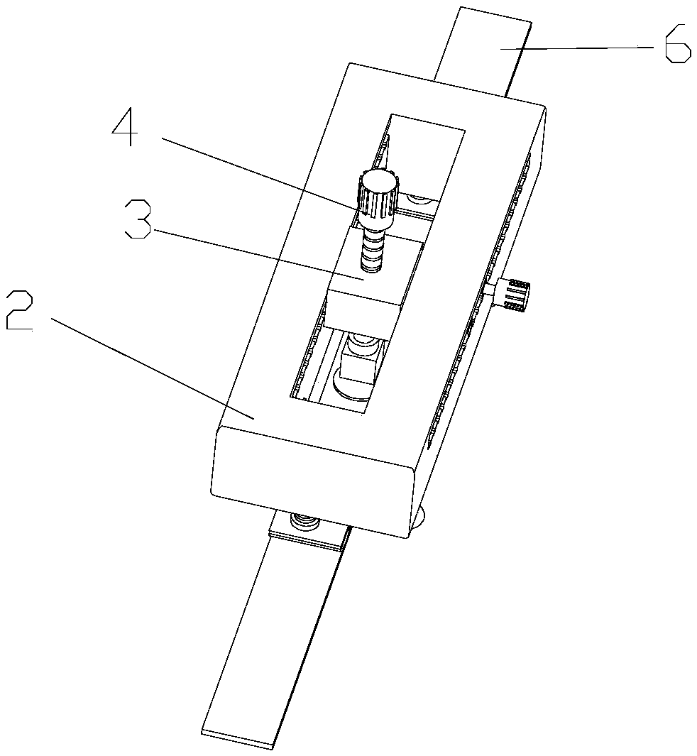
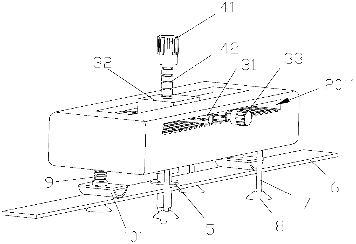
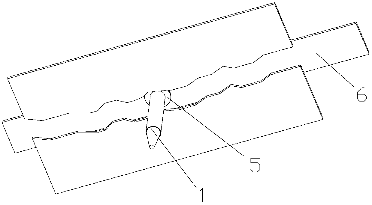
[0043] Such as Figure 1-3 As shown, the present invention discloses an automatic grouting device for concrete crack defects with high adhesion strength, which includes a grouting pipe 1 through which concrete grout is injected into concrete cracks. It also includes a frame 2, an electric sliding part 3, an electric lifting part 4, a rubber sleeve 5, a brickwork knife 6, a first support rod 7, a first suction cup 8, a second support rod 9, and a conflicting part 101. The electric sliding part 3 is slidingly matched with the frame 2, the electric lifting part 4 is set on the electric sliding part 3, the lifting end of the electric lifting part 4 is connected with the grout filling pipe 1, and the brick knife 6 is set on the grout filling pipe through the rubber sleeve 5 1's periphery. One end of the first support rod 7 and one end of the second support rod 9 are all arranged on the frame 2, wherein, the other end of the first support rod 7 can extend toward the position direct...
Embodiment 2
[0047] Such as Figure 4 As shown, the difference between this embodiment and the above-mentioned embodiments is that the first suction cup 8 is provided with an air suction port 81, and a circle of pressing structure 82 extends on the edge of the first suction cup 8, and a sliding fit is also provided on the first support rod 7. The pressing piece 83 can be pressed against the pressing structure 82 .
[0048]If the concrete wall or board surface is relatively rough or the frame 2 has a large self-weight, it may be difficult to generate sufficient suction force only by manually pressing the first suction cup 8 on the concrete wall or board surface. At this time, By opening an air suction port 81 on the first suction cup 8, the excess air in the first suction cup 8 is further sucked out, and the vacuum degree of the first suction cup 8 is further increased to further increase the suction force. Moreover, by pressing down the pressing member 83 to the pressing structure 82 at t...
Embodiment 3
[0050] Such as Figure 5-7 As shown, the difference between this embodiment and the above-mentioned embodiments is that a first supporting telescopic member 21 is provided at the end of the frame 2, and the first supporting telescopic member 21 includes a first fixed hollow tube 211, at least one first movable Hollow tube 212, the size of the section of each first movable hollow tube 212 is not the same, the first movable hollow tube 212 with smaller cross-sectional size can be sleeved on the first movable hollow tube 212 with larger cross-sectional size Among the hollow parts, the first hollow tube with the largest cross-sectional size can be sleeved in the hollow part of the first fixed hollow tube 211 . In the first fixed hollow tube 211 and the first movable hollow tube 212, there are mounting threaded holes (not shown in the figure), the mounting threaded holes of the first fixed hollow tube 211, the first movable hollow tubes The mounting threaded holes in 212 correspon...
PUM
 Abstract
Description
Claims
Application Information
 - R&D
- Intellectual Property
- Life Sciences
- Materials
- Tech Scout
- Unparalleled Data Quality
- Higher Quality Content
- 60% Fewer Hallucinations
Browse by: Latest US Patents, China's latest patents, Technical Efficacy Thesaurus, Application Domain, Technology Topic, Popular Technical Reports.
© 2025 PatSnap. All rights reserved.Legal|Privacy policy|Modern Slavery Act Transparency Statement|Sitemap|About US| Contact US: help@patsnap.com


