
An X-ray dynamic image system of explosive foil flyers

A technology of dynamic imaging and explosive foil, which is applied in the field of high-speed X-ray imaging, can solve the problems of expensive and complex implementation, and achieve the effect of simple implementation and flexible adjustment

Pending Publication Date: 2018-12-25
LASER FUSION RES CENT CHINA ACAD OF ENG PHYSICS
View PDF0 Cites 9 Cited by
  • Summary
  • Abstract
  • Description
  • Claims
  • Application Information

AI Technical Summary

Problems solved by technology

The traditional X-ray high-speed imaging method uses a pulsed X-ray generator and a high-speed X-ray camera to dynamically image the explosive foil flyer. This method requires expensive and large-scale special equipment, and requires a pulsed X-ray generator and a high-speed X-ray camera. The precise synchronous matching between them is technically very complicated, and a simplified method is needed to realize the X-ray dynamic imaging of explosive foil flyers

Method used


Image

  • An X-ray dynamic image system of explosive foil flyers
  • An X-ray dynamic image system of explosive foil flyers
  • An X-ray dynamic image system of explosive foil flyers

Examples


Embodiment 1

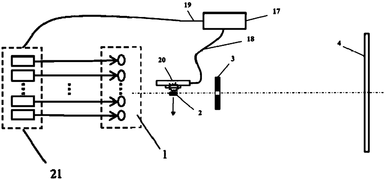
[0027] see figure 1 , which is a schematic structural diagram of an explosive foil flyer X-ray dynamic imaging system provided in an embodiment of the present application. An explosive foil flyer X-ray dynamic imaging system includes a signal synchronization device 20 , a pulsed laser array 21 , a metal target array 1 , a small-hole imaging plate 3 and a recording medium 4 .

[0028] The signal synchronization device 20 is used for outputting electrical pulse sequences.

[0029] It should be noted that the number of electric pulses in the electric pulse sequence can be adjusted according to actual needs, and the number of electric pulses determines the number of dynamic images of the explosive foil flyer that can be obtained. The time interval of the electrical pulse sequence can be the same, that is, a periodic sequence of pulses, or the time interval can be different, which is a sequence of pulses with variable period.

[0030] Each laser of the pulsed laser array 21 is us...

Embodiment 2

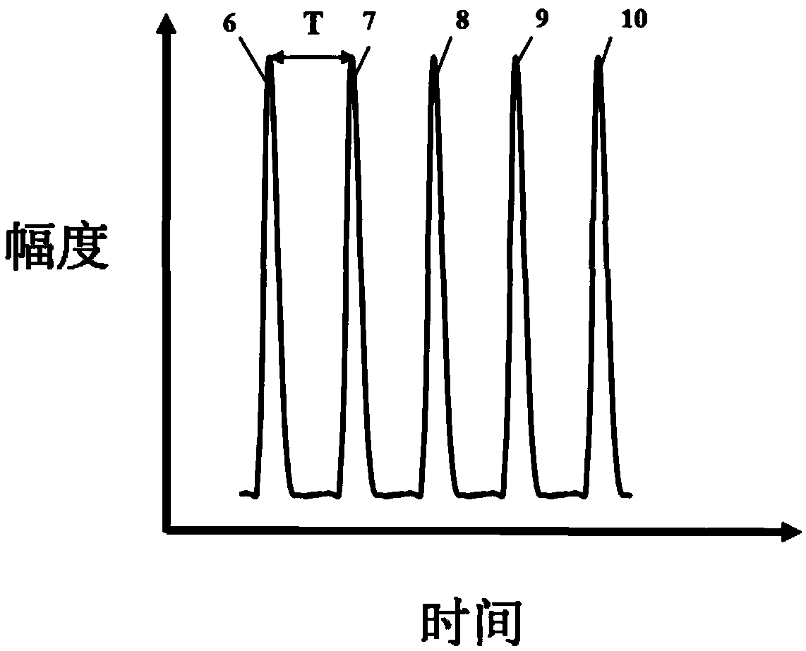
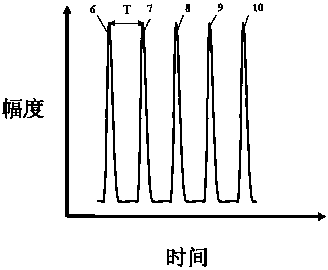
[0042] Hereinafter, based on the above embodiments, taking the electric pulse sequence including 5 electric pulses as an example, an explosive foil flyer X-ray dynamic imaging system of this embodiment will be described in detail.

[0043] see figure 2 , which is another structural schematic diagram of an explosive foil flyer X-ray dynamic imaging system provided in this embodiment. The metal target array includes a first metal target 11, a second metal target 12, a third metal target 13, a fourth metal target 14 and a fifth metal target 15, and each metal target is arranged at equal intervals, while in the metal target array The target surface normal of each metal target is perpendicular to the small hole imaging plate. The metal target is mounted on the base 5 through a metal rod 16 .

[0044] The metal target array 1 , the pinhole imaging plate 3 , the explosive foil device 20 to be tested and the recording medium 4 are aligned with each other.

[0045] The explosive fo...


PUM


Abstract

An X-ray dynamic image system of explosive foil flyers is provided. Each metal target in the metal target array is sequentially irradiated with a laser pulse sequence including a plurality of laser pulses, the corresponding X-ray pulse sequence is generated to irradiate the explosive foil flyer at different flight positions at different time points, and the corresponding X-ray images are obtainedat different positions on a recording medium, so that the time-resolved X-ray imaging is realized. In addition, the system can adjust the period of laser pulse sequences, the number of laser pulses and the number of metal targets in the metal target array according to the actual needs, so as to adjust the period of the X-ray pulse sequence, the number of X-ray pulses and the intensity of single pulse X-rays, to realize the dynamic multi-image imaging of explosive foil flyers; the system has the characteristics of simple realization mode and flexible adjustment.

Description

technical field [0001] The invention belongs to the field of high-speed X-ray imaging, and in particular relates to an X-ray dynamic imaging system for explosive foil flying pieces. Background technique [0002] Explosive foil is an electrical explosive device. A large current is injected into the metal foil instantaneously to generate considerable energy accumulation, which causes the explosive foil to explode and eject high-speed flying pieces to detonate the explosive. In the research of explosive foil, it is necessary to take pictures of the flying state of the flying pieces produced by the explosion foil detonation, and judge the detonation effect by analyzing the speed and shape of the impacting flying pieces, so as to provide a basis for the optimal design. X-ray is a kind of short-wavelength radiation with strong penetrating ability. The dynamic imaging of flying flakes by X-ray can obtain the internal structure information of the object without destroying the struct...

Claims


Application Information

Patent Timeline
IPC IPC(8): G03B42/02
CPCG03B42/02
Inventor 易涛郑万国江少恩杨家敏
Owner LASER FUSION RES CENT CHINA ACAD OF ENG PHYSICS
Learn More