Application method of paralyzed-patient nursing system

A nursing system and technology for paralyzed patients, applied in hospital beds, medical science, non-surgical orthopedic operations, etc., can solve the problems of troublesome rehabilitation exercise and frequent massage process for paralyzed patients, complicated cleaning work for paralyzed patients, high difficulty in moving paralyzed patients, and achieve Improve comfort and quality of life, avoid muscle atrophy, and promote the recovery of body functions

Active Publication Date: 2018-12-28
深圳市中科创想科技有限责任公司
View PDF7 Cites 3 Cited by
  • Summary
  • Abstract
  • Description
  • Claims
  • Application Information

AI Technical Summary

Problems solved by technology

[0005] It is very difficult for paralyzed patients to move for physical examination and daily living. The movement needs to be manually moved or tied up with a safety rope, which is very labor-intensive and can easily cause discomfort for paralyzed patients; The work is complicated, and the process of rehabilitation exercise and frequent massage for paralyzed patients is troublesome, which is also a difficult point in the nursing work of paralyzed patients

Method used


Image

  • Application method of paralyzed-patient nursing system
  • Application method of paralyzed-patient nursing system
  • Application method of paralyzed-patient nursing system

Examples


Embodiment 1

[0053] A method for using a nursing system for paralyzed patients, the nursing system for paralyzed patients includes a nursing bed, a transfer wheelchair 4 and a massage mechanism 5;

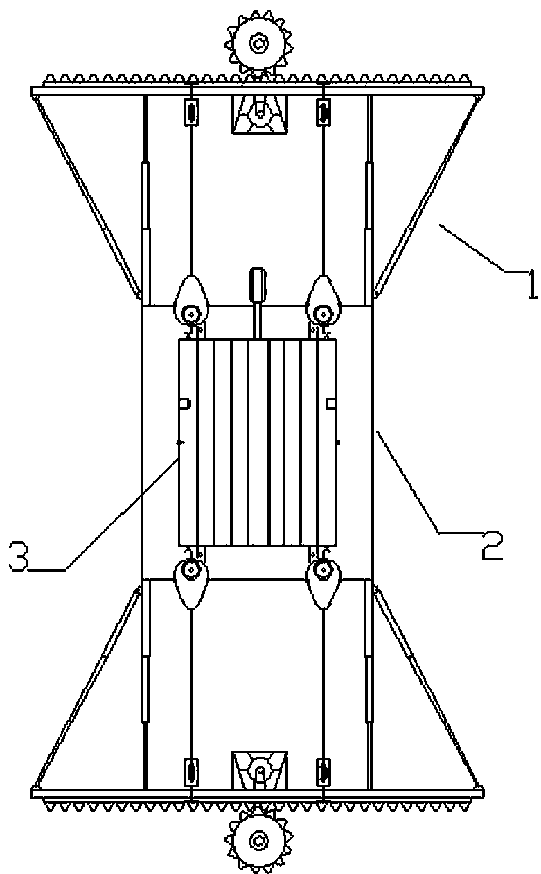
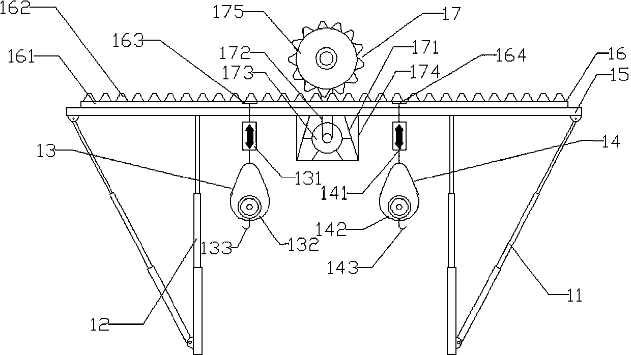
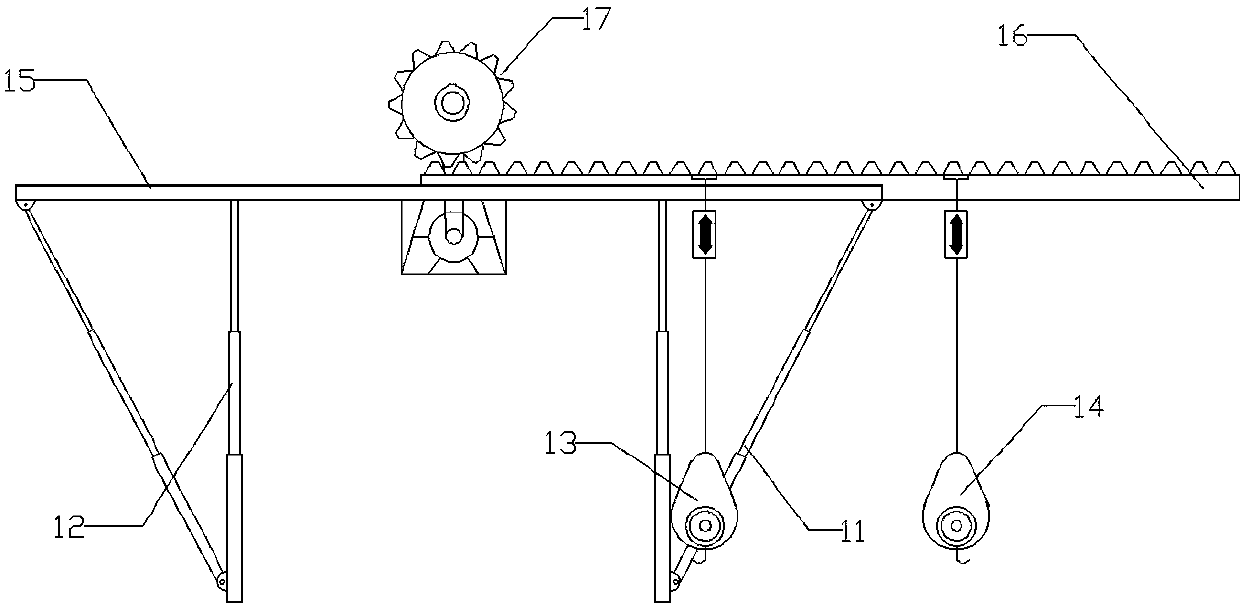
[0054] The nursing bed includes a translation mechanism 1 , a bed body 2 and a moving bed board 3 . The translation mechanism 1 is symmetrically arranged on the head and tail of the bed body 2 , the bed legs of the bed body 2 are liftable bed legs, and the movable bed board 3 is arranged on the upper surface of the bed body 2 . The translation mechanism 1 includes a symmetrically arranged oblique support rod 11 , a symmetrically arranged vertical support rod 12 , a first lifter 13 , a second lifter 14 , a translation track 15 , a translation slider 16 and a gear mechanism 17 . The bottom end of the vertical support rod 12 is detachably mounted on the four corners of the bed body 2, and the top end supports the translation track 15; one end of the oblique support rod 11 is hinged to the bottom o...

Embodiment 2

[0068] The difference between this embodiment and Embodiment 1 is that the wheelchair frame 47 also includes a front wheel vertical bar 4711 , a front wheel cross bar 4712 , a rear wheel vertical bar 4721 , an oblique link 4722 and a horizontal link 4723 . The front wheel cross bar 4712 supports the front wheel vertical bar 4711, the oblique connecting rod 4722 supports the front wheel vertical bar 4711 and the rear wheel vertical bar 4721, and the horizontal connecting rod 4723 supports the baffle 473, the front wheel vertical bar 4711 and the rear wheel 472.

Embodiment 3

[0070]The difference between this embodiment and Embodiment 2 is that: the transfer wheelchair 4 also includes a toilet assembly 48, and the toilet assembly 48 is arranged in the bottom plate of the groove plate 421; the toilet assembly 48 includes a groove body 481, Sewage pipe 482, water inlet pipe 483, flushing branch pipe 484, cleaning branch pipe 487, flushing ring pipe 485, drying fan and wireless controller. The flush water branch pipe 484 communicates with the flush water ring pipe 485, and the bottom of the flush water ring pipe 485 is provided with a plurality of water spray ports. The drying fan is arranged above the flushing ring pipe 485 on the inner wall of the tank body 481; the first electromagnetic one-way valve 486 is arranged in the flushing branch pipe 484, and the second electromagnetic one-way valve 488 is arranged in the cleaning branch pipe 487. A heater 489 is arranged on the top of the cleaning branch pipe 487, and a spray nozzle is arranged at the mo...


PUM


Abstract

The invention discloses an application method of paralyzed-patient nursing system. The paralyzed-patient nursing system comprises a nursing bed, a transferring wheelchair and a massage mechanism. Theapplication method has the advantages that various comprehensive requirements of paralyzed-patient nursing are satisfied, manual carrying is not needed, the nursing procedures are simplified, the comfortableness and living quality of a paralyzed patient are improved, and body function recovery is promoted.

Description

technical field [0001] The invention relates to the technical field of medical auxiliary devices, in particular to a method for using a nursing system for paralyzed patients. Background technique [0002] The incidence of paralysis in our country has always been high. No matter what the cause is, it makes the patient unable to exercise and loses the same vitality as other people. Paralysis, the reduction or loss of voluntary movement, is a common symptom of the nervous system and is the result of a disease of the nerves, neuromuscular junction, or muscles. Nursing care for paralyzed patients is difficult, and paralyzed patients have many complications, which has troubled more and more families. [0003] Publication No. CN104546320A discloses a bathing transfer system for paralyzed elderly people, including a base frame, a lifting portion arranged on the base frame, a support portion arranged at the upper end of the lifting portion, and a support portion arranged under the s...

Claims


Application Information

Patent Timeline
Patent Type & Authority Applications(China)
IPC IPC(8): A61G7/00A61G7/05A61F5/00
CPCA61F5/00A61G7/00A61G7/05
Inventor 马纯胡小兵
Owner 深圳市中科创想科技有限责任公司
Why Eureka
Try Eureka