Toilet bowl with simple flushing device and toilet bowl washing method

A toilet, simple technology, applied to flushing equipment with water tank, water supply device, sanitary equipment for toilets, etc. simple structure

Pending Publication Date: 2018-12-28
XIAMEN R&T PLUMBING TECH
View PDF10 Cites 3 Cited by
  • Summary
  • Abstract
  • Description
  • Claims
  • Application Information

AI Technical Summary

Problems solved by technology

[0002] At present, with the improvement of living standards, the flushing function of the toilet is gradually diversified to meet the needs of users, especially the flushing cooperation between the toilet brush ring water channel and the main flush water channel, and the water supply to the brush ring water channel through the water inlet mechanism. The flushing of the inner wall of the toilet is to supply water to the water tank through the water inlet mechanism to supply water to the main flushing channel. Therefore, it is necessary to meet the control of the water supply timing of the brush ring water channel and the control of the water intake of the toilet tank, while the prior art In the water stop component of the water inlet mechanism, there is only one pressure relief hole on the back pressure chamber, which is difficult to meet the diverse control requirements of the water inlet mechanism

Method used


Image

  • Toilet bowl with simple flushing device and toilet bowl washing method
  • Toilet bowl with simple flushing device and toilet bowl washing method
  • Toilet bowl with simple flushing device and toilet bowl washing method

Examples


no. 1 example

[0054] The first embodiment: (the water inlet mechanism and the drainage mechanism are integrally arranged)

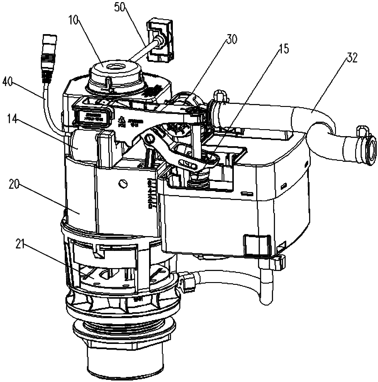
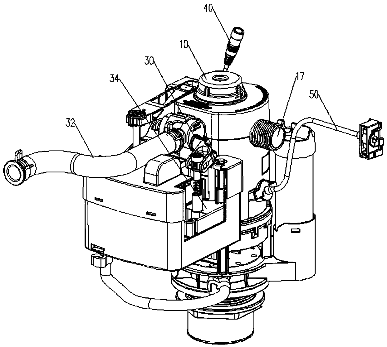
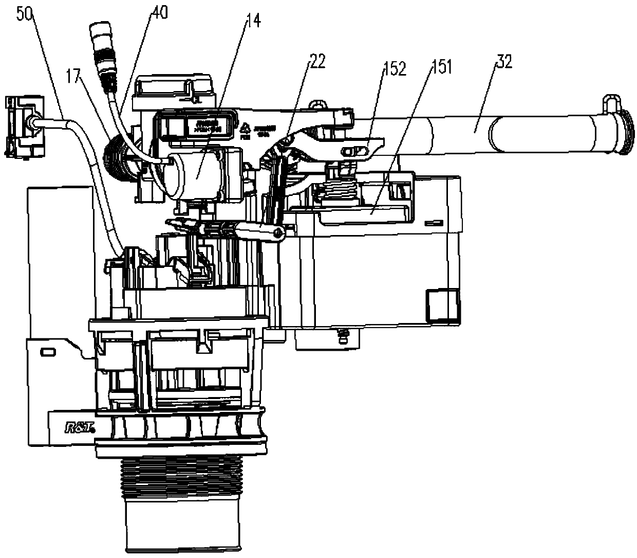
[0055] Such as Figure 1 to Figure 11 As shown, a toilet with a simple flushing device, the toilet (not shown) includes a brush ring water channel (not shown) for flushing the inner wall of the urinal (not shown) and a main flush connected to the bottom of the urinal Waterways (not shown), also include:

[0056] A water tank (not shown) has a water tank cavity for storing flushing water, and the water tank is provided with a drainage channel (not shown) connecting the water tank cavity and the main flushing channel;

[0057] The water inlet mechanism 10 includes a water stop unit that opens or closes the water inlet mechanism 10, and the water stop unit includes a back pressure chamber (not shown in the figure) that is provided with a first pressure relief hole 12 and a second pressure relief hole 13 shown), when both the first pressure relief hole 12 and the second ...

no. 2 example

[0082] The second embodiment: (the water inlet mechanism and the drainage mechanism are independently arranged)

[0083] Such as Figure 12 to Figure 19 As shown, the difference between this embodiment and the above-mentioned embodiments is that the water inlet mechanism 10 and the water discharge mechanism adopt independent water inlet valves and water discharge valves, and there is no linkage between the floating bucket assembly 15 and the valve core 21, Such as Figure 18 and Figure 19 As shown, when the first starting unit 50 is started, the buoy bucket 151 opens the second pressure relief hole 13 as the water level in the inner cavity of the water tank drops to enable the water inlet mechanism 10 to start water intake, and the electronically controlled The component 14 controls the first pressure relief hole 12 to close before the second pressure relief hole 13 is closed, and the buoy 151 rises with the water level in the water tank to close the second pressure relief ...

no. 3 example

[0084] The third embodiment: (switching mechanism with injection function)

[0085] Such as Figure 20 to Figure 23 As shown, the difference between this embodiment and the first embodiment is that the switching mechanism 30 of this embodiment also includes a spray pipe 36 and a nozzle 35 communicating with the water outlet channel 11, and the nozzle 35 is connected to the spray pipe 36 The two ends of the spray pipe 36 are arranged at intervals, and the two ends of the spray pipe 36 are respectively connected with the water channel of the brush ring and the inner cavity of the water tank. , the switching member 31 is arranged on the spray pipe 36, so that the water outlet channel 11 is sprayed to the water channel of the brush ring or the inner cavity of the water tank through the nozzle 35. This structure is a prior art and will not be repeated here.

[0086] The present invention also proposes a toilet flushing method using the toilet with a simple flushing device in any o...


PUM


Abstract

The invention discloses a toilet bowl with a simple flushing device. The toilet bowl comprises a brush ring water channel, a main washing water channel, a water tank, a water inflow mechanism and a drainage mechanism. The water inflow mechanism comprises a water stop unit for switching on or off the water inflow mechanism. The water stop unit comprises a backpressure cavity with a first pressure relief hole and a second pressure relief hole. When the first pressure relief hole and the second pressure relief hole are both closed, the water inflow mechanism is switched off, and when at least oneof the first pressure relief hole and the second pressure relief hole is open, the water inflow mechanism is switched on. When the water inflow mechanism is switched on, a water outflow channel of the water inflow mechanism supplies water to the brush ring water channel or an inner cavity of the water tank. The toilet bowl further comprises a first start unit for starting the drainage mechanism for drainage. According to the scheme, the two pressure relief holes are formed in the backpressure cavity, control over the water inflow mechanism is more flexible and diverse, the use requirements ofdifferent functions can be met, and the toilet bowl is simple in structure and reliable in function. The invention further provides a washing method of the toilet with the simple flushing device.

Description

technical field [0001] The invention relates to a toilet with a simple flushing device and a toilet flushing method. Background technique [0002] At present, with the improvement of living standards, the flushing function of the toilet is gradually diversified to meet the needs of users, especially the flushing cooperation between the toilet brush ring water channel and the main flush water channel, and the water supply to the brush ring water channel through the water inlet mechanism. The flushing of the inner wall of the toilet is to supply water to the water tank through the water inlet mechanism to supply water to the main flushing channel. Therefore, it is necessary to meet the control of the water supply timing of the brush ring water channel and the control of the water intake of the toilet tank, while the prior art In the water stop assembly of the water inlet mechanism, there is only one pressure relief hole in the back pressure chamber, which is difficult to meet ...

Claims


Application Information

Patent Timeline
Patent Type & Authority Applications(China)
IPC IPC(8): E03D9/08E03D1/24E03D5/10
CPCE03D1/24E03D5/10E03D9/08
Inventor 张凤荣黄贵阳钟志军
Owner XIAMEN R&T PLUMBING TECH
Why Eureka
Try Eureka