

Electronic control ammonia injection system
An electronically controlled injection and ammonia technology, which is applied to the electronic control, exhaust treatment, and exhaust devices of exhaust gas treatment devices, can solve the influence of quantitative injection of ammonia gas, unstable flow rate, and difficulty in matching the amount of ammonia gas with exhaust gas. The need for purification, etc.
Pending Publication Date: 2018-12-28
科林蓝泰环境科技(长春)有限公司
View PDF0 Cites 0 Cited by
- Summary
- Abstract
- Description
- Claims
- Application Information
AI Technical Summary
Problems solved by technology
On the basis of this design, there are still some problems in how to put the ammonia gas stored in the storage tank into use efficiently and accurately, especially because the ammonia storage tank releases ammonia gas at different rates in different environments, resulting in the output flow rate of Unstable, which affects the quantitative injection of ammonia gas later, and the amount of ammonia gas injected is difficult to match the demand for exhaust gas purification
Method used
View moreImage
Smart ImageViewing Examples

Examples
Embodiment Construction
Login to View More PUM
 Abstract
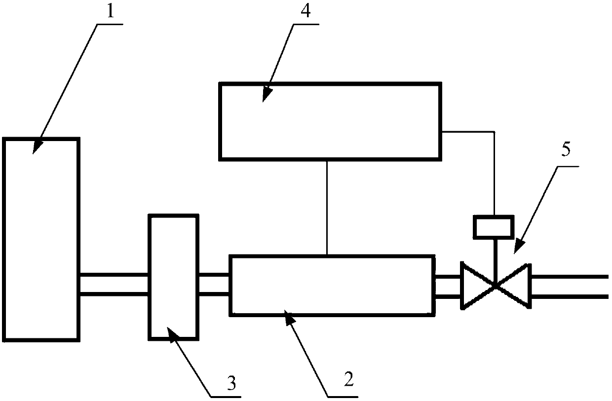
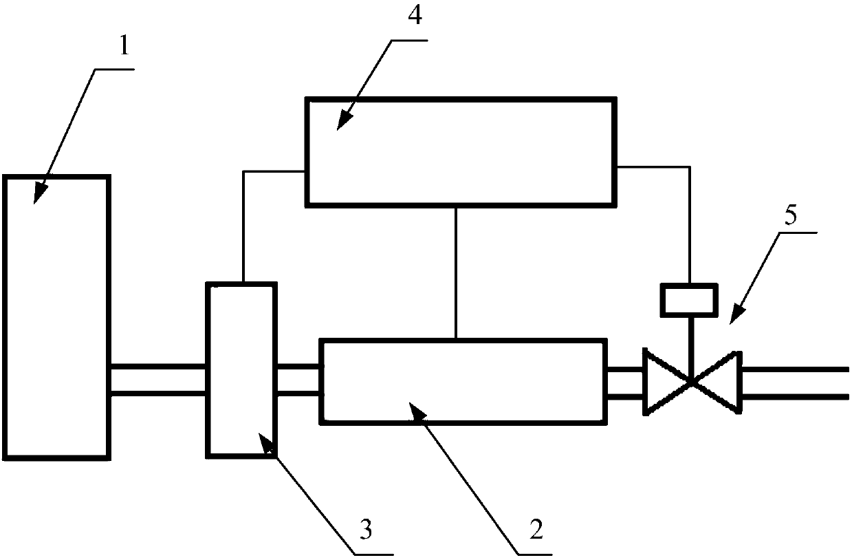
The invention discloses an electronic control ammonia injection system. The electronic control ammonia injection system comprises an ammonia storage tank, a flow collecting device and a pressure regulating valve, wherein the ammonia storage tank is used for storing and releasing ammonia, the flow collecting device is communicated with the ammonia storage tank and an ammonia output pipe for metering throughput of ammonia; the pressure regulating valve is arranged on the pipe between the ammonia storage tank and the flow collecting device for controlling the output pressure of the ammonia storage tank. The output pipe of the ammonia storage tank is provided with the flow collecting device to acquire of the jet flow of ammonia, thereby achieving the aim of precise output; the output end of the ammonia storage tank is provided with the structure of the pressure regulating valve to control the output pressure of the ammonia storage tank within a preset range, thereby achieving the effect ofstable output, effectively ensuring precise control and measurement of the ammonia output of the subsequent output process, ensuring that the output ammonia can meet the practical demands of exhaustpurification and avoiding waste leakage or incomplete purification.
Description
technical field The invention relates to the technical field of automobile tail gas purification, in particular to an ammonia electronically controlled injection system. Background technique The exhaust gas treatment device of the automobile is mainly a device that purifies the exhaust gas under the action of the catalyst to reduce the pollution to the environment. Automobile exhaust is the exhaust gas produced by the use of automobiles. It contains hundreds of different compounds. The pollutants include solid suspended particles, carbon monoxide, carbon dioxide, hydrocarbons, nitrogen oxides, lead and sulfur oxides. At present, the mainstream exhaust gas purification equipment is realized by catalyst. When high-temperature automobile exhaust gas passes through the purification device, the purifier in the catalyst will enhance the activity of CO, HC and NOx gases, and promote certain redox chemical reactions. In order to change the harmful gas into a harmless gas, so that ...
Claims
Login to View More Application Information
Patent Timeline
 IPC IPC(8): F01N3/20F01N9/00
CPCF01N3/2066F01N3/208F01N9/00F01N2610/02F01N2610/146Y02T10/40
Inventor郝赫
Owner科林蓝泰环境科技(长春)有限公司