A method and apparatus for computing a matrix of a polar coordinate system in a two-dimensional reconstruction algorithm

A system matrix and reconstruction algorithm technology, applied in the field of optical measurement, can solve the problems of numerical calculation error, low calculation efficiency, and reduced calculation accuracy.

Active Publication Date: 2018-12-28
PLA PEOPLES LIBERATION ARMY OF CHINA STRATEGIC SUPPORT FORCE AEROSPACE ENG UNIV
View PDF8 Cites 5 Cited by
  • Summary
  • Abstract
  • Description
  • Claims
  • Application Information

AI Technical Summary

Problems solved by technology

There are two problems with this grid division method. One is that when the projection angle changes, the system matrix must be recalculated for each iteration, which is inefficie...

Method used


Image

  • A method and apparatus for computing a matrix of a polar coordinate system in a two-dimensional reconstruction algorithm
  • A method and apparatus for computing a matrix of a polar coordinate system in a two-dimensional reconstruction algorithm
  • A method and apparatus for computing a matrix of a polar coordinate system in a two-dimensional reconstruction algorithm

Examples


Embodiment 1

[0092] The object processed in Embodiment 1 and the comparative example: a typical example of grid division in polar coordinates. The field of view area is a circle with a radius of 90.5mm, which is divided into 200 concentric circles at equal intervals in the radial direction, with a pitch of 0.4525mm, and then divided into 360 equal parts in the azimuth direction with a step of 1° , constructing a total of 72000 polar coordinate grids. The distance from the light source to the center of the circle is 800mm, and the distance from the center of the circle to the detector is 200mm. The number of detector elements is 512, and the pitch is 0.5mm. Calculate the polar coordinate system matrix according to the above analysis method, and the calculation time is 13s (Intel Core i5 CPU, 4G DDR3).

Embodiment 1 2

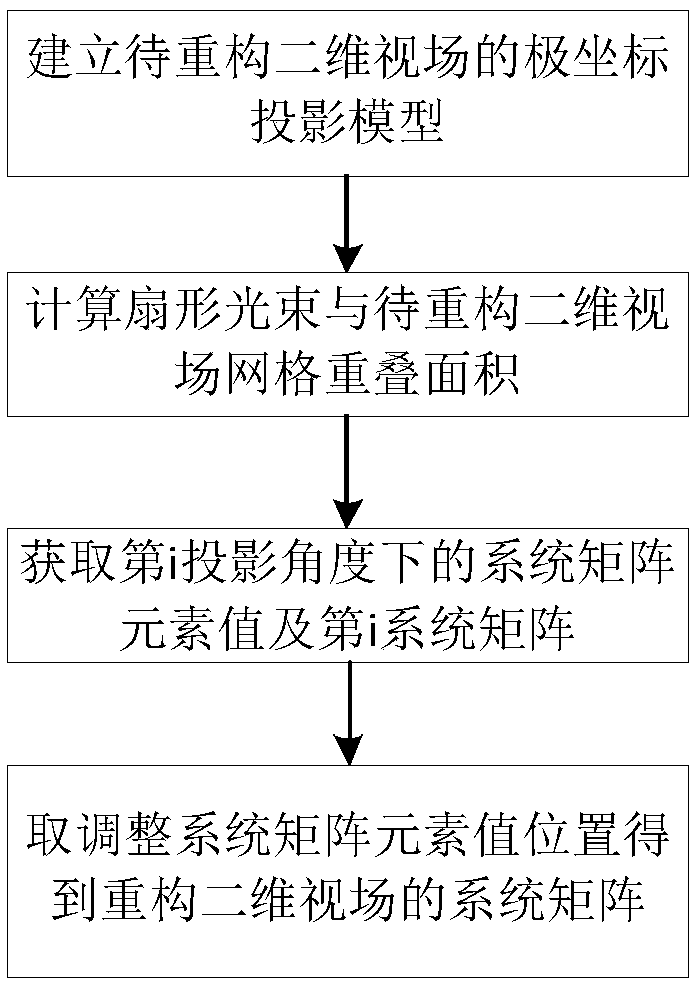
[0093] Example 1 Calculation Method of Polar Coordinate System Matrix in Two-dimensional Reconstruction Algorithm

[0094] Step S100: Establishing a polar coordinate projection model of the 2D field of view to be reconstructed

[0095] The fan-shaped beam projection model based on polar coordinate grid division of the present invention is as follows Figure 4 shown. The origin of the polar coordinates is located at the center of the field of view, and the radius of the field of view is R. In actual situations, the effective field of view is not completely circular, but needs to be contained within the circular field of view. The structure of the detector array can be linear or fan-shaped. The present invention uses a linear array as an example for illustration. It is assumed that the detector array includes M primitives, and the length of each primitive is d. The distance from the light source S to the detector array is D, the vertical line passes through the origin of the ...


PUM


Abstract

The invention discloses a method and a device for calculating a polar coordinate system matrix in a two-dimensional reconstruction algorithm. The method comprises the following steps: S100: establishing a polar coordinate projection model of a two-dimensional field of view to be reconstructed; S200, calculating the overlapping area of the projection beam and the polar coordinate grid at the i-th projection angle as a system matrix element value amn, wherein m in the subscript is a detector primitive number and n is a grid numb; S300: traversing and calculating all overlapping areas under the projection angle to obtain the system matrix A= {amn} of the two-dimensional field of view to be reconstructed. The system matrix under other projection angles can be obtained by adjusting the positionof the system matrix element value in the system matrix according to the change of the projection angle without repeated calculation. The method can improve the precision of algebraic iterative two-dimensional reconstruction algorithm, and avoid recalculating the system matrix when the projection angle changes, and improve the computational efficiency. Another aspect of the invention also provides an apparatus for use in the method.

Description

technical field [0001] The invention relates to a method and device for calculating a polar coordinate system matrix in a two-dimensional reconstruction algorithm, belonging to the field of optical measurement. Background technique [0002] Computed Tomography (CT) based on the principle of spectral absorption has been maturely applied in the field of medical imaging, and can provide clear two-dimensional reconstructed images for medical diagnosis. Due to the universality of this method, it can be combined with Tunable Diode Laser Absorption Spectroscopy (TDLAS) to achieve two-dimensional reconstruction of the temperature and concentration of the engine combustion flow field. CT reconstruction algorithms mainly include Filtered Back Projection (FBP) and Algebraic Reconstruction Technique (ART). Compared with the FBP method, the ART method has very good reconstruction accuracy and noise level, and does not require complete projection data. [0003] But the ART method is sev...

Claims


Application Information

Patent Timeline
IPC IPC(8): G06T11/00
CPCG06T11/006G06T2210/41G06T2211/40
Inventor 饶伟王广宇宋俊玲冯高平王明东
Owner PLA PEOPLES LIBERATION ARMY OF CHINA STRATEGIC SUPPORT FORCE AEROSPACE ENG UNIV
Why Eureka
Try Eureka