
A mechanical DC circuit breaker topology

A technology of DC circuit breaker and topology structure, applied in emergency protection circuit devices, electrical components, etc., can solve the problem of doubts about the reliability of DC circuit breakers, and achieve the effect of small attenuation and reliable shutdown

Pending Publication Date: 2018-12-28
SHANDONG POWER EQUIP
View PDF0 Cites 7 Cited by
  • Summary
  • Abstract
  • Description
  • Claims
  • Application Information

AI Technical Summary

Problems solved by technology

[0004] In the topology of existing DC circuit breakers, the breaking reliability of DC circuit breakers has always been doubted

Method used


Image

  • A mechanical DC circuit breaker topology
  • A mechanical DC circuit breaker topology
  • A mechanical DC circuit breaker topology

Examples


Embodiment Construction

[0020] The above is only an overview of the technical solution of the present invention. In order to better understand the technical means of the present invention, the present invention will be further described in detail below in conjunction with the accompanying drawings and specific embodiments.

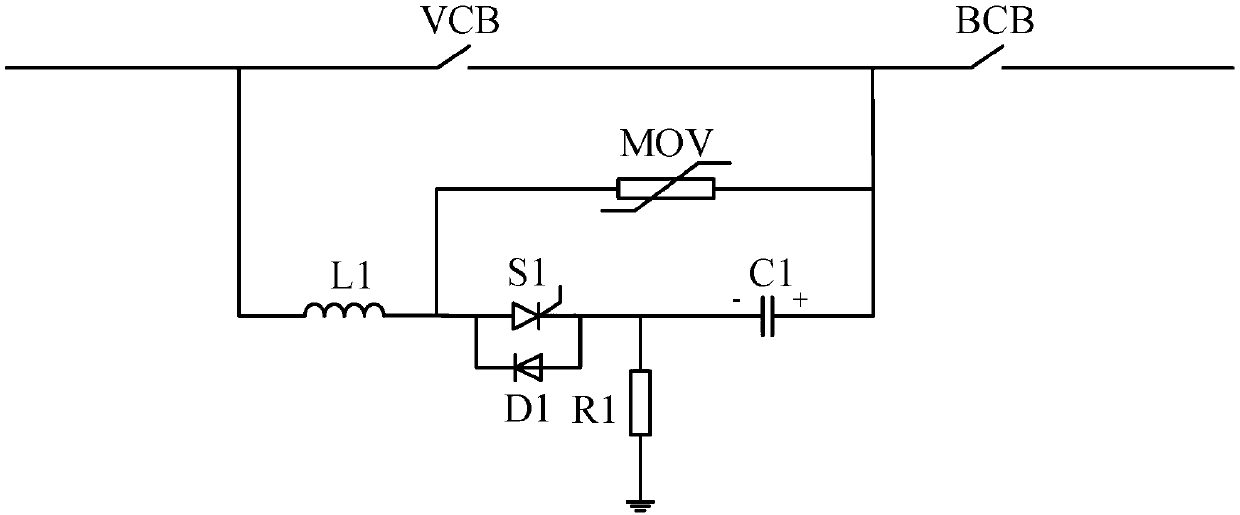
[0021] as attached figure 1 As shown, a mechanical DC circuit breaker topology includes an auxiliary circuit breaker BCB for cutting off residual current and three parallel branches. The first branch is composed of a main circuit breaker VCB for conducting the normal operating current of the system. The main circuit breaker VCB adopts an operating mechanism composed of an electromagnetic repulsion mechanism and a permanent magnet mechanism. The outlet end of the main circuit breaker VCB is connected to the inlet end of the auxiliary circuit breaker BCB; the second branch is a commutation branch, including the inductor L1 , Thyristor S1, diode D1, resistor R1, commutation charging...


PUM


Abstract

The invention relates to a mechanical DC circuit breaker topology, comprising an auxiliary circuit breaker for cutting off the residual current and three parallel branches. The first branch consists of a main circuit breaker for conducting the normal working current of the system. The second branch is commutation branch. The third branch is the energy release branch. The commutated charging capacitor in the invention can be charged by the transmission line without installing a charging machine for charging the commutated charging capacitor. When the HVDC transmission system is short-circuited,the reverse current to be put in will generate multiple oscillations, and the attenuation is small, so that the transmission line current appears multiple zero crossing points, so that the mechanicalHVDC circuit breaker can be reliably turned off.

Description

technical field [0001] The invention belongs to the technical field of DC circuit breakers, in particular to a mechanical DC circuit breaker topology. Background technique [0002] With the rapid development of flexible DC transmission, in order to ensure the safe operation of DC transmission system, a reliable DC breaking scheme is urgently needed. In the AC transmission system, the AC current passes through the zero point twice in each cycle, and the circuit breaker can use these two current zero points to break. But in the DC transmission system, the current does not have a zero-crossing point, so it is more difficult to break the current. [0003] The DC breaking method based on artificial zero-crossing is an important method in the high-voltage DC breaking technology scheme. Artificial zero-crossing breaking technology has been researched and applied in the field of low voltage, and corresponding research has been carried out in the field of medium voltage and high vo...

Claims


Application Information

Patent Timeline
IPC IPC(8): H02H7/26
CPCH02H7/268
Inventor 颜世凯谈翀于建斌王思祥白长玉王坤张玉舒吕腾飞张曼玉
Owner SHANDONG POWER EQUIP
Learn More