A method and apparatus for monitoring the synchronous state of a line protection pilot channel
A technology of synchronous state and line protection, applied in the direction of emergency protection circuit devices, circuit devices, parts of emergency protection devices, etc., can solve problems such as inability to monitor, small load current of transmission lines, and no clear threshold of differential current, etc., to achieve implementation The effect of convenience and simple circuit
Active Publication Date: 2018-12-28
NR ELECTRIC CO LTD +1
View PDF5 Cites 4 Cited by
- Summary
- Abstract
- Description
- Claims
- Application Information
AI Technical Summary
Problems solved by technology
This monitoring method is greatly affected by capacitive current and sampling accuracy, and there is no clear differential current threshold to distinguish normal and abnormal states; and the load current of transmission lines is small, so it cannot be monitored
Method used
View moreImage
Smart ImageViewing Examples
Examples
Embodiment Construction
Login to View More PUM
 Abstract
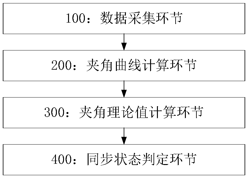
The invention discloses a method for monitoring the synchronous state of a line protection pilot channel. The method comprises the steps of: step 100: collecting transmission line parameters and electric quantities on the two sides and then performing the step 200; step 200, calculating a relationship curve between the theoretical value of the included angle of the two sides and the theoretical value of the current of the own side according to the line equivalent model by using the collected line parameters and the electric quantities of the two sides, and then executing step 300; step 300, obtaining the theoretical value of the included angle of the two sides current and the theoretical value of the included angle of the two sides voltage according to the calculation result in the step 200 and the electric quantity of the two sides collected in the step 100, and then executing the step 400; step 400, according to the calculation result of step 300 and the electric quantities on both sides collected in step 100, determining the synchronization state of the line protection pilot channel by error analysis. At the same time, the invention discloses a corresponding apparatus for monitoring the synchronous state of a line protection pilot channel. This method does not depend on GPS pairs and is not affected by load current.
Description
technical field The invention belongs to the technical field of power grid relay protection, and in particular relates to a method and a device for monitoring the synchronous state of a transmission line protection longitudinal channel. Background technique Transmission line current differential protection is a kind of transmission line main protection, and its theoretical basis is Kirchhoff's current theorem. When the transmission line is working normally or there is a fault outside the area, ignoring the influence of the distributed capacitance of the line, the current flowing into the line is equal to the current flowing out, the differential current is zero, and the differential relay does not operate. When the transmission line internal fault, ignoring the influence of line distributed capacitance, the differential current is equal to the fault current flowing into the line, and the differential relay operates. The principle of current differential protection is simple...
Claims
Login to View More Application Information
Patent Timeline
 IPC IPC(8): H02H7/26H02H1/00
CPCH02H1/0007H02H7/26
Inventor 李奔赵青春徐晓春谢华谈浩戴光武刘奎陆金凤王玉龙陈建国
Owner NR ELECTRIC CO LTD
Features
- R&D
- Intellectual Property
- Life Sciences
- Materials
- Tech Scout
- Unparalleled Data Quality
- Higher Quality Content
- 60% Fewer Hallucinations
Learn More Browse by: Latest US Patents, China's latest patents, Technical Efficacy Thesaurus, Application Domain, Technology Topic, Popular Technical Reports.
© 2025 PatSnap. All rights reserved.Legal|Privacy policy|Modern Slavery Act Transparency Statement|Sitemap|About US| Contact US: help@patsnap.com


