Electric pipe cleaning device

A technology for cleaning devices and power pipelines, applied in the field of power equipment, can solve problems such as low efficiency and poor effect, and achieve the effect of ingenious structure setting

Inactive Publication Date: 2019-01-01
胡沛
View PDF3 Cites 14 Cited by
  • Summary
  • Abstract
  • Description
  • Claims
  • Application Information

AI Technical Summary

Problems solved by technology

[0003] The inner wall of the power pipeline needs to be cleaned during maintenance and cleaning of the power pipeline. However, the traditional cleaning method uses manual cleaning, which is inefficient and ineffective

Method used


Image

  • Electric pipe cleaning device
  • Electric pipe cleaning device
  • Electric pipe cleaning device

Examples


Embodiment 1

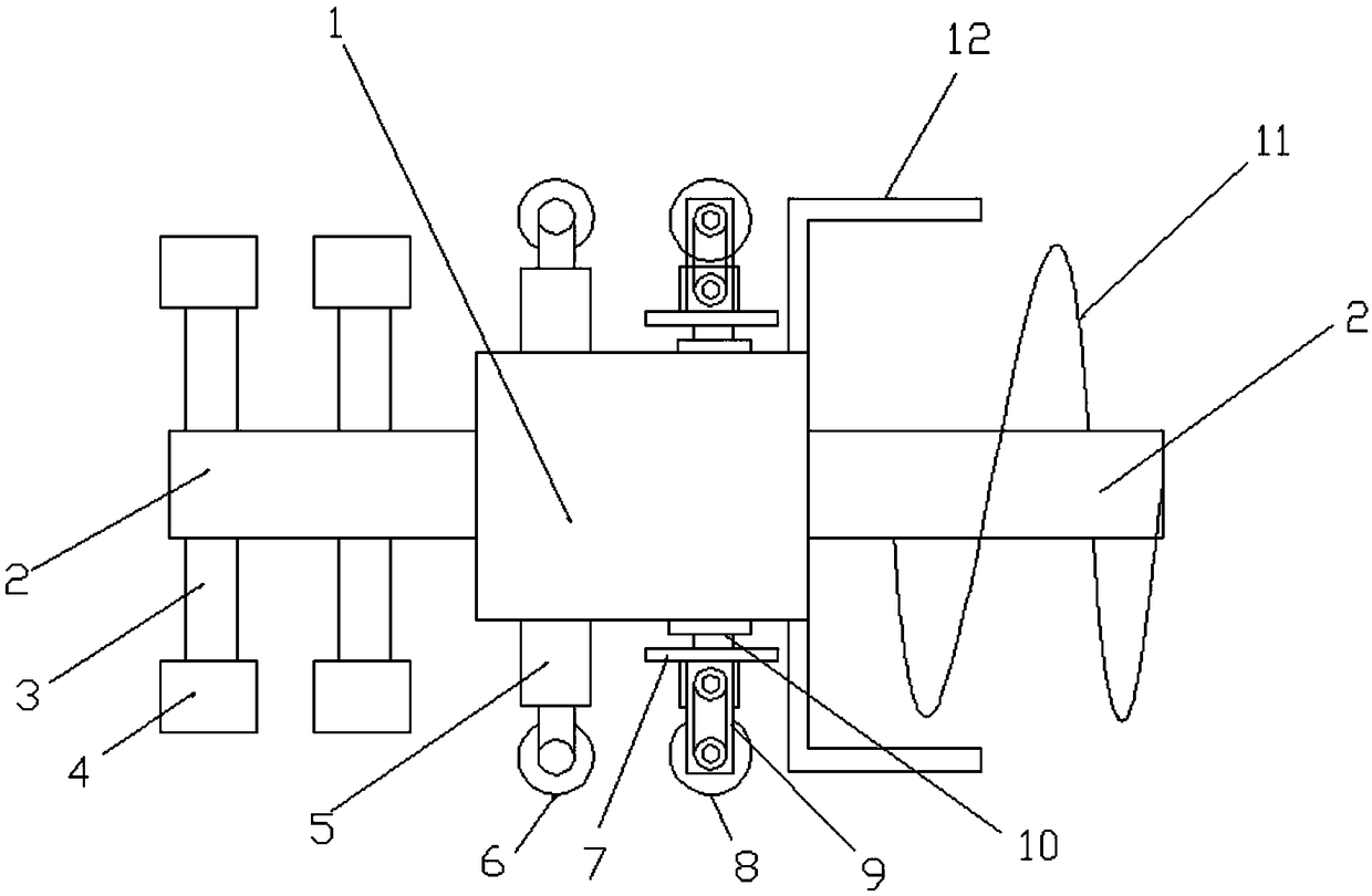
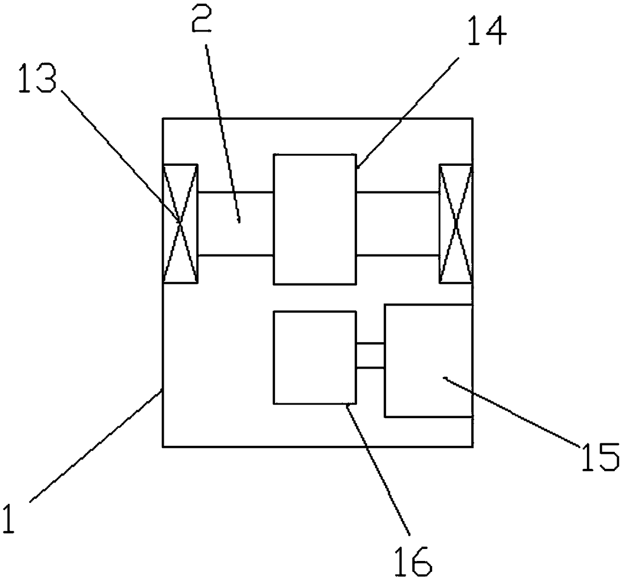
[0021] Example 1: See Figure 1~4 , in an embodiment of the present invention, a power pipeline cleaning device includes a machine compartment 1, a horizontal rotating shaft 2 runs through the machine compartment 1, and the transverse rotating shaft 2 is set on fixed bearings 13 provided at corresponding positions on both sides of the machine compartment 1, The machine compartment 1 is provided with a horizontal shaft drive mechanism, and the front side of the machine compartment 1 is evenly provided with an elastic telescopic bracket 3 on the horizontal shaft, and the outer end of the elastic telescopic bracket 3 is provided with a wiper 4. The upper and lower sides are provided with traveling mechanisms, and the rear end of the cabin 1 is provided with an aggregate storage mechanism.

[0022] The drive mechanism of the horizontal shaft includes a driven gear 14, which is sleeved on the horizontal shaft 2 in the cabin 1, and the cabin 1 is provided with a driving gear 16 and ...

Embodiment 2

[0028] Embodiment 2: The only difference between this embodiment and Embodiment 1 is the technical feature: the cylinder 10 is replaced by an elastic telescopic bracket.

[0029] The working principle of the present invention is: the present invention provides a power pipeline cleaning device with ingenious structure and reasonable arrangement

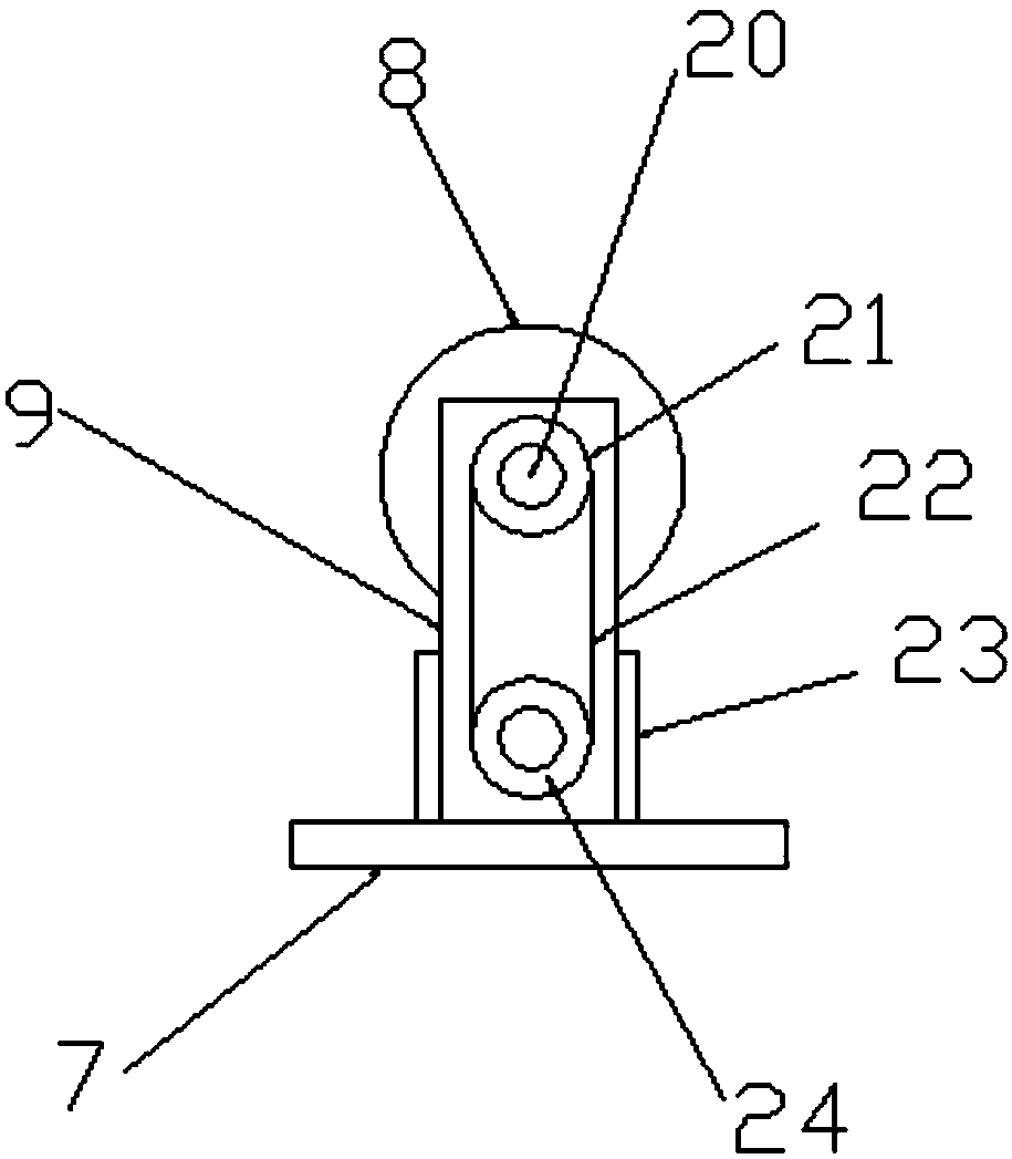
[0030] When working, the machine compartment is placed in the power pipeline, and the scraper on the horizontal shaft abuts against the inner wall of the power pipeline under the elastic force of the telescopic spring, and the horizontal shaft is driven to clean the inner wall of the power pipeline. The cylinder drives the travel wheel to touch the inner wall of the power pipeline, and the travel wheel is driven to drive the engine compartment to move along the inner wall of the pipeline, thereby realizing the moving scraping brush cleaning, the scraper scrapes off the garbage on the inner wall of the power pipeline, and the horizontal ...


PUM


Abstract

The invention discloses an electric pipe cleaning device. The electric pipe cleaning device comprises a machine bin; a transverse rotating shaft penetrates through the machine bin, and sleeves fixed bearings arranged in the corresponding positions on two sides of the machine bin; a transverse rotating shaft driving mechanism is arranged in the machine bin; elastic extension brackets are uniformlyarranged on the transverse rotating shaft on the front side of the machine bin; scraping brushes are arranged at the outer ends of the elastic extension brackets; walking mechanisms are arranged on the upper and lower sides of the machine bin; a collection and storage mechanism is arranged at the back end of the machine bin; the transverse rotating shaft driving mechanism comprises a driven gear;and the driven gear sleeves the transverse rotating shaft in the machine bin. The electric pipe cleaning device is skillful in structural setting and reasonable in arrangement, and realizes cleaning of the inner walls of electric pipes through movement of the scraping brushes; garbage on the inner walls of the electric pipes is scraped off by the scraping brushes; the transverse rotating shaft inthe collection and storage mechanism is driven to drive spiral blades to rotate; and the spiral blades push the garbage to enter a collecting cylinder to realize automatic cleaning.

Description

technical field [0001] The invention relates to the technical field of power equipment, in particular to a power pipeline cleaning device. Background technique [0002] Power equipment mainly includes power generation equipment and power supply equipment. Power generation equipment is mainly power plant boilers, steam turbines, gas turbines, water turbines, generators, transformers, etc. Power supply equipment is mainly transmission lines of various voltage levels, transformers, contactors, etc. Devices, etc., and the power pipe is a product that uses PE (modified polyethylene) for hot dipping or epoxy resin for internal and external coating, and has excellent corrosion resistance. At the same time, the coating itself has good electrical insulation and will not cause electrical corrosion. Low water absorption, high mechanical strength, small friction coefficient, can achieve the purpose of long-term use. It can also effectively prevent damage to plant roots and soil enviro...

Claims


Application Information

Patent Timeline
Patent Type & Authority Applications(China)
IPC IPC(8): B08B9/051
CPCB08B9/051
Inventor 胡沛
Owner 胡沛
Why Eureka
Try Eureka