Flying shear crankshaft mechanism

A technology of flying shears and crankshafts, applied in the direction of shearing devices, shearing machine equipment, shearing machine accessories, etc., can solve the problems of low shearing strength and inability to shear high-strength sheets, and achieve strong shearing Strength, increase the applicable range, and the effect of easy operation

Pending Publication Date: 2019-01-01
HANGZHOU HENGLI CUTTING EQUIP
View PDF0 Cites 1 Cited by
  • Summary
  • Abstract
  • Description
  • Claims
  • Application Information

AI Technical Summary

Problems solved by technology

[0002] On the plate blanking processing line, it is necessary to realize the shearing process of the plate during the operation of the plate. The flying shear is an important equipment responsible for shearing in the flying shear line. The shear strength of the flying shear in the prior art is Generally low, not suitable for shearing high-strength sheets

Method used


Image

  • Flying shear crankshaft mechanism
  • Flying shear crankshaft mechanism

Examples


Embodiment Construction

[0022] The present invention will be described in further detail below in conjunction with the accompanying drawings and specific embodiments.

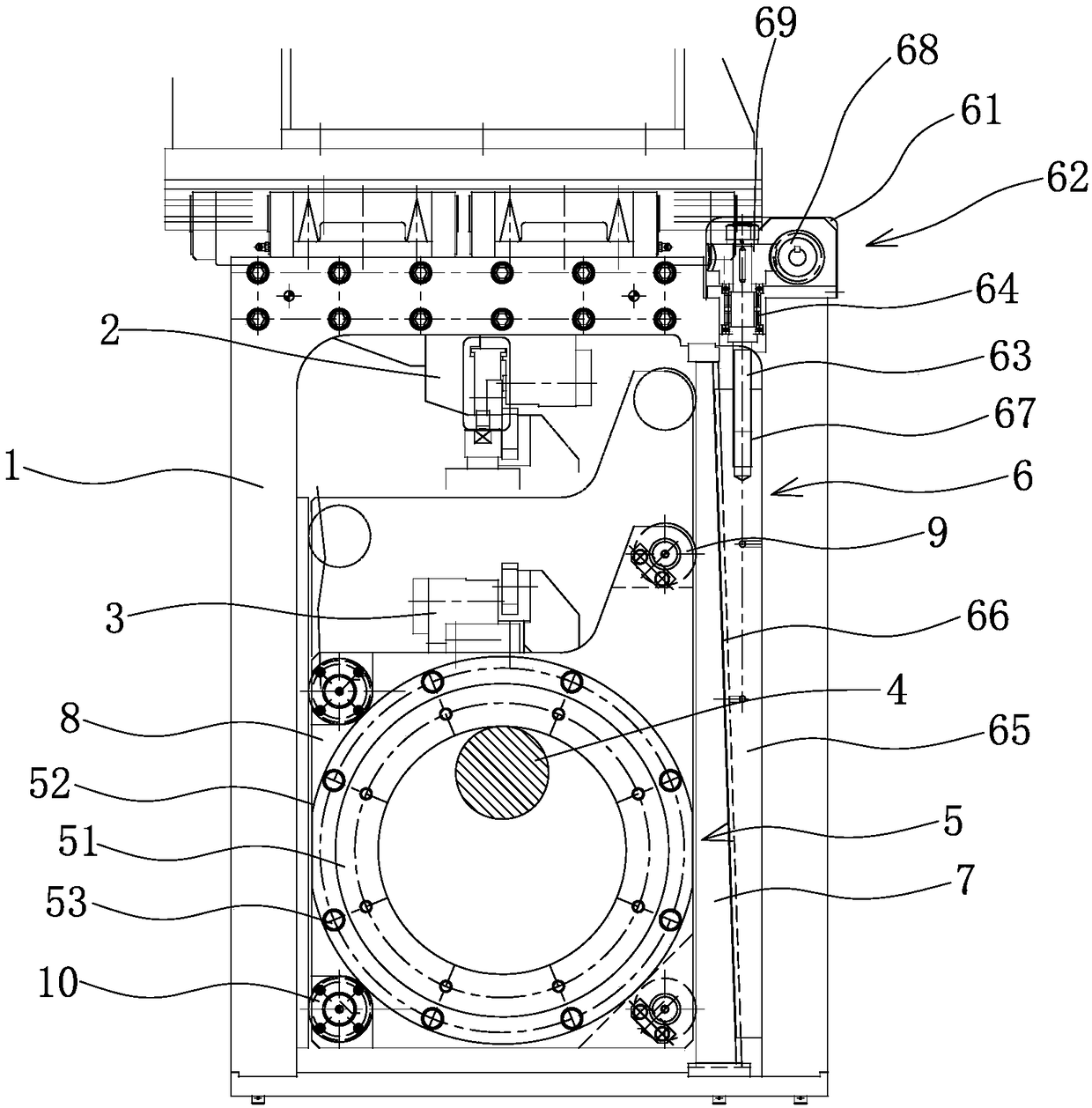
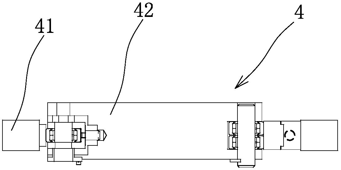
[0023] combine figure 1 and figure 2 Shown, a kind of flying shears crankshaft mechanism comprises frame 1, and fixed cutter 2 and sliding cutter 3 that are arranged oppositely, described fixed cutter 2 is fixedly connected with frame 1, and sliding cutter 3 is slidably connected with frame 1, Also includes a crank mechanism 4, said crank mechanism 4 is rotationally connected with the frame 1 or arranged outside the frame 1, the present invention does not limit the specific position of the crank mechanism 4, it can be rotatably connected to the frame 1, or can be set Outside the frame 1, the sliding cutter 3 is pressed on the outer surface of the push ring 5, and the inner surface of the push ring 5 is pressed on the outer surface of the crank mechanism 4. Turning the crank mechanism 4 can make the slide cutter 3 approach Or move a...


PUM


Abstract

The invention belongs to the technical field of shearing equipment, and particularly relates to a flying shear crankshaft mechanism comprising a rack, and a fixed cutter and a sliding cutter which arearranged oppositely; the fixed cutter is connected to the rack fixedly, and the sliding cutter is connected to the rack slidably; the flying shear crankshaft mechanism further comprises a crankshaftmechanism body rotatably connected to the rack or arranged on the outside of the rack; the sliding cutter is arranged on the outside surface of a push ring by pressing, and the inside surface of the push ring is arranged on the outside surface of the crankshaft mechanism body by pressing; and the sliding cutter can be moved closely to or far away from the fixed cutter through the crankshaft mechanism body. According to the flying shear crankshaft mechanism, the push ring is pushed back and forth through rotation of the crankshaft mechanism body, so that the reciprocating shearing of a flying shear is achieved, and accordingly the higher shearing strength of the flying shear in the shearing process is ensured; and the flying shear crankshaft mechanism is easy to operate during regulation ofa clearance between the cutters, and is higher in regulation accuracy.

Description

technical field [0001] The invention belongs to the technical field of shearing equipment, in particular to a crankshaft mechanism of a flying shear. Background technique [0002] On the plate blanking processing line, it is necessary to realize the shearing process of the plate during the operation of the plate. The flying shear is an important equipment responsible for shearing in the flying shear line. The shear strength of the flying shear in the prior art is Generally low, not suitable for shearing high-strength sheets. Contents of the invention [0003] The object of the present invention is to provide a kind of flying shears crankshaft mechanism for above-mentioned problem. [0004] To achieve the above object, the present invention adopts the following technical solutions: [0005] A kind of flying shears crankshaft mechanism, comprises frame, and fixed cutter and sliding cutter that are oppositely arranged, and described fixed cutter is fixedly connected with fr...

Claims


Application Information

Patent Timeline
Patent Type & Authority Applications(China)
IPC IPC(8): B23D25/02B23D33/00
CPCB23D25/02B23D33/00
Inventor 韩波丁力
Owner HANGZHOU HENGLI CUTTING EQUIP
Why Eureka
Try Eureka