Novel grinding tool
A new type of grinding tool technology, applied in abrasives, manufacturing tools, metal processing equipment, etc., can solve the problems of high production cost, high cost of abrasive tool use, difficulty in meeting surface quality requirements, etc., achieve optimal treatment effect, convenient replacement, The effect of reducing the cost of use
- Summary
- Abstract
- Description
- Claims
- Application Information
AI Technical Summary
Problems solved by technology
Method used
Image

Examples
Embodiment 1
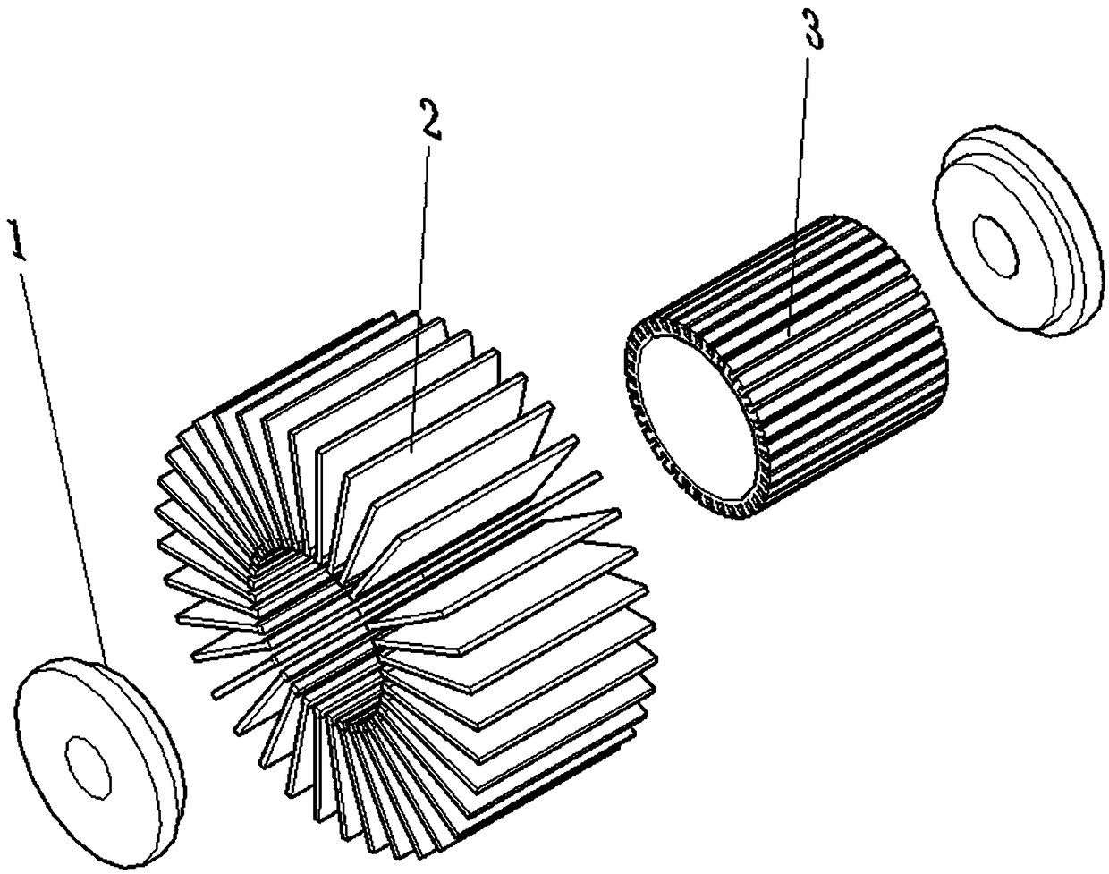
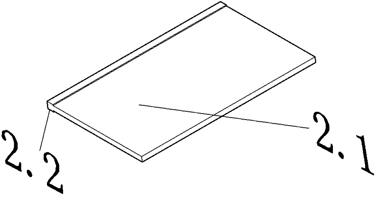
[0036] The invention proposes a new type of abrasive tool, which solves the shortcomings of the prior art that the surface treatment of aluminum materials is not complete, resulting in poor surface quality of aluminum materials. The mechanical polishing of the surface can completely remove the burrs and metal particles on the surface of the aluminum material. It has the characteristics of low labor intensity and high efficiency, such as Figure 1~Figure 4 As shown, the following setting structure is specially adopted: including a grinding core 3, and a grinding brush 2 is detachably arranged on the outer circumference of the grinding core 3; The grinding brush 2 is formed on the outer periphery of the grinding core 3, and the detachable setting method can be a snap connection, a screw connection or an auxiliary connection, which can achieve that the grinding brush 2 and the grinding core 3 can be easily separated. Yes, when in use, when the grinding brush 2 or grinding core 3 ...
Embodiment 2
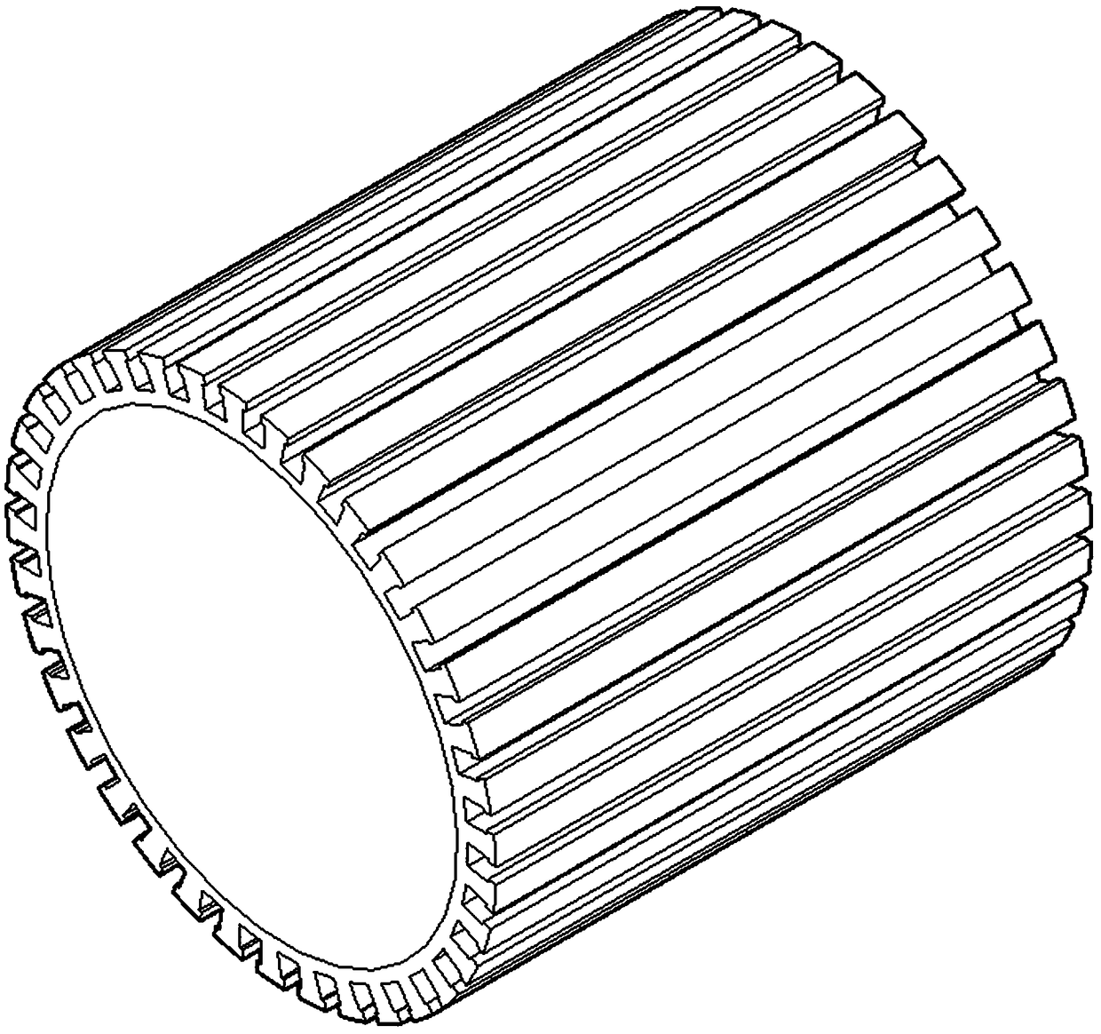
[0038] This embodiment is further optimized on the basis of the above-mentioned embodiment, and further to better realize the present invention, such as Figure 1~Figure 4 As shown, the following arrangement structure is particularly adopted: at least one connecting groove 3.1 is opened on the outer circumference of the grinding core 3 along the radial or circumferential direction. As a preferred arrangement, at least one connecting groove is provided on the outer periphery of the grinding core 3 along the radial or circumferential direction (the connecting groove can be detachably connected to the grinding brush by means of snap connection, screw connection or auxiliary fittings) ) 3.1, preferably, the opening of connecting grooves can be carried out according to an even number or a base number; or a connecting groove is opened on the surface of the grinding core 2 in a lattice shape (that is, the connecting groove is a non-circumferential or radial single connected shape) 3.1...
Embodiment 3
[0040] This embodiment is further optimized on the basis of any of the above-mentioned embodiments, and further to better realize the present invention, such as Figure 1~Figure 4 As shown, the following setting structure is specially adopted: the connecting groove 3.1 is a square groove, a triangular groove, a trapezoidal groove or a T-shaped groove; The connecting groove 3.1 adopts any one of a square groove, a triangular groove, a trapezoidal groove, a T-shaped groove, etc.; a pattern can be set in the connecting groove 3.1, so that the grinding brush 2 and the connecting groove 3.1 cooperate more closely.
PUM
 Abstract
Description
Claims
Application Information
 - R&D
- Intellectual Property
- Life Sciences
- Materials
- Tech Scout
- Unparalleled Data Quality
- Higher Quality Content
- 60% Fewer Hallucinations
Browse by: Latest US Patents, China's latest patents, Technical Efficacy Thesaurus, Application Domain, Technology Topic, Popular Technical Reports.
© 2025 PatSnap. All rights reserved.Legal|Privacy policy|Modern Slavery Act Transparency Statement|Sitemap|About US| Contact US: help@patsnap.com