
Winding device for enameled wire production and processing technique thereof

A winding device and enameled wire technology, which are applied in the directions of transportation and packaging, transportation of filamentous materials, and thin material handling, etc., can solve the problems of enameled wire vibration, unsatisfactory winding effect, and inability to use reels, so as to avoid vibration, Easy to promote and use, easy to operate

Pending Publication Date: 2019-01-01
天长市嘉通铜业有限公司
View PDF0 Cites 2 Cited by
  • Summary
  • Abstract
  • Description
  • Claims
  • Application Information

AI Technical Summary

Problems solved by technology

[0003] In order to solve the above problems, the present invention discloses a winding device based on enameled wire production and its processing technology. The number of enameled coils on the reel is small, and the reel cannot be fully utilized. At the same time, the enameled wire will vibrate due to the relationship between the winding shaft during the winding process, resulting in an unsatisfactory winding effect.

Method used


Image

  • Winding device for enameled wire production and processing technique thereof
  • Winding device for enameled wire production and processing technique thereof
  • Winding device for enameled wire production and processing technique thereof

Examples


Embodiment 1

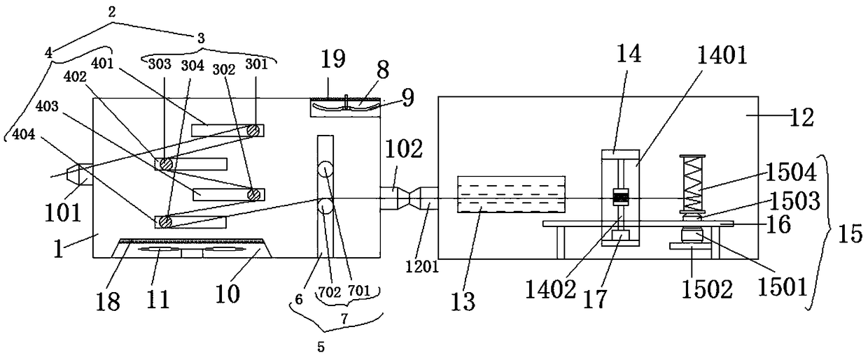
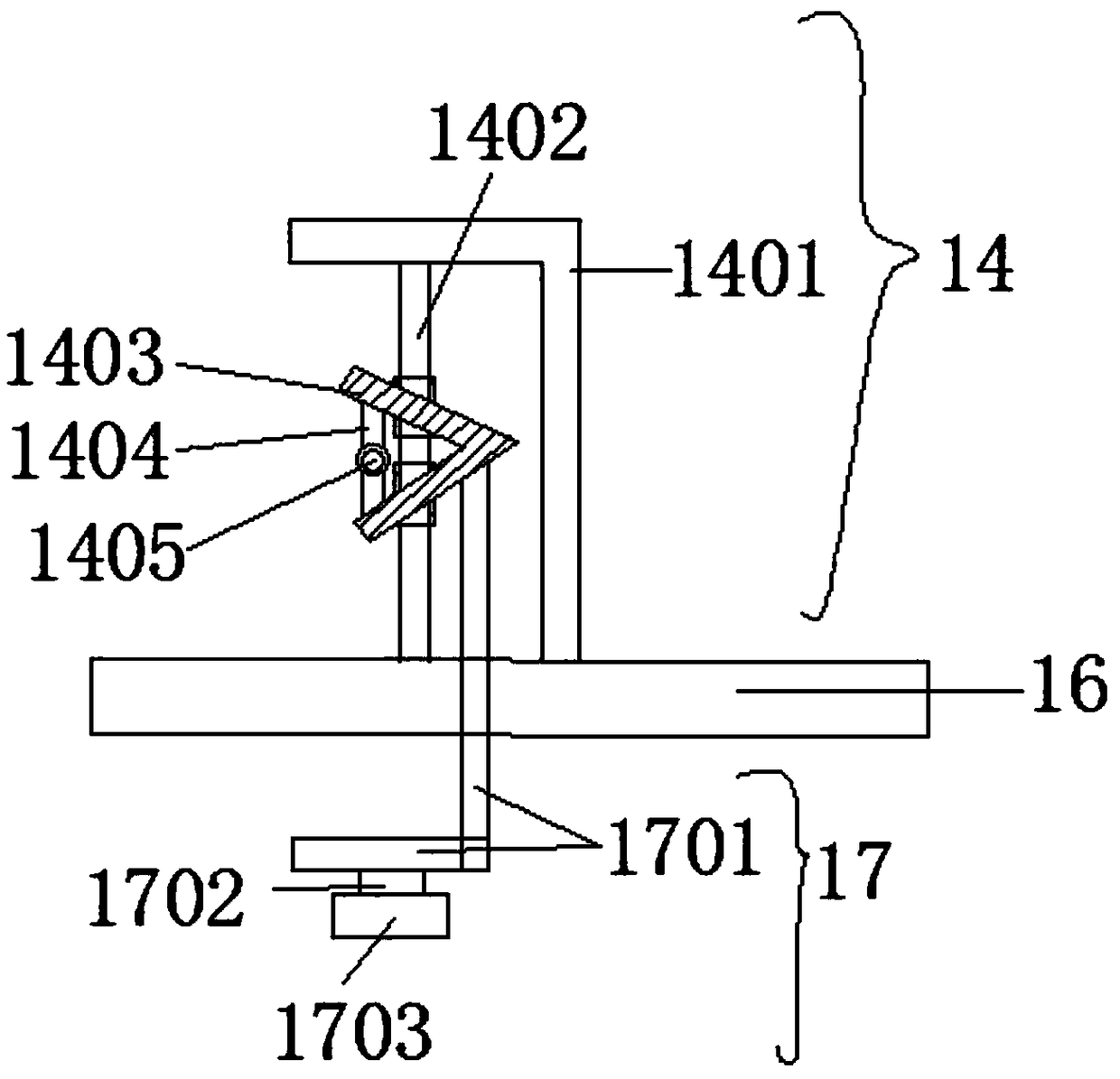
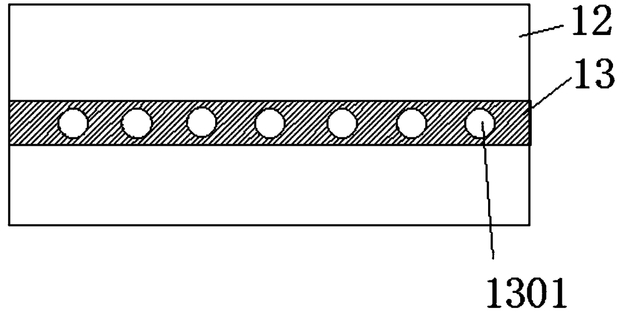
[0021] Embodiment 1: see figure 1 , figure 2 and image 3 Now, a kind of winding device based on enameled wire production provided by the present invention will be described, including a lead box 1, the front end of the lead box 1 is provided with a wire inlet 101, and the rear end of the lead box 1 is provided with an outlet port 102, the lead wire assembly 2 is provided inside the lead box body 1, and the lead wire assembly 2 includes a lead roll set 3, and the lead roll set 3 includes a lead roll, specifically a first lead roll 301, a second lead roll 302 , the third lead roller 303 and the fourth lead roller 304, the lead roller group 3 is installed inside the lead box body 1 through the strap group 4, and the strap group 4 is formed from top to bottom in the lead box body 1 The first board 401, the second board 402, the third board 403 and the fourth board 404 are formed, the right side of the board group 4 is provided with a transmission assembly 5, and the transmissi...

Embodiment 2

[0022] Example 2: see figure 1 , figure 2 and image 3 , as an improvement of the present invention, the upper end of the air outlet cavity 10 is provided with a filter 18 , and the upper end of the air inlet cavity 8 is provided with a filter layer 19 .

Embodiment 3

[0023] Embodiment 3: see figure 1 , figure 2 and image 3 , As an improvement of the present invention, the filter 18 adopts a HEPA filter, and the filter layer 19 adopts a bamboo charcoal filter layer.


PUM


Abstract

The invention discloses a winding device for enameled wire production and a processing technique thereof. The winding device comprises a leading box body and a winding box body, wherein a leading assembly is arranged in the leading box body, the leading assembly comprises a leading roller group, the leading roller group is installed in the leading box body by virtue of a butt plate group, a winding displacement plate, a winding displacement group and a winding group are arranged in the winding box body in sequence, the winding displacement group comprises a winding displacement base which is installed on a winding platform, an installation sliding seat sleeves a connecting rod, a leading rod is installed on one end of the sliding seat, a leading hole is formed in the middle of a rod body of the leading rod, and an up-and-down adjusting assembly which is used for supplying a power source to the winding displacement group is arranged on the lower end of the winding platform. Enameled wires can be lifted up and down at uniform speed by the adjusting assembly during winding, the enameled wires are uniformly wound on a winding reel, so that the enameled wires are convenient to wind, additionally, the leading roller group in the leading box body is used cooperatively, so that the enameled wires are prevented from vibrating, and the processing technique has the advantages of simplicity and convenience in popularization.

Description

technical field [0001] The invention relates to the technical field of enameled wire processing, in particular to a winding device for enameled wire production and a processing technology thereof. Background technique [0002] Copper-clad aluminum enameled wire is a new type of electromagnetic wire that uses copper-clad aluminum as the inner conductor. Its characteristics are between copper and aluminum, combining the excellent conductivity of copper and the advantages of light weight of aluminum. After the production of the enameled wire is completed, it must be wound on a reel to facilitate the subsequent storage, use, transportation and sales of the enameled wire. However, after the existing enameled wire winding device is wound on the reel, the enameled wire is relatively loose, resulting in a small number of enameled coils wound on the reel, and the reel cannot be fully utilized. The relationship between the spools will vibrate, resulting in an unsatisfactory winding e...

Claims


Application Information

Patent Timeline
Patent Type & Authority Applications(China)
IPC IPC(8): B65H54/28B65H57/06B65H51/08B65H59/18
CPCB65H51/08B65H54/28B65H57/06B65H59/18
Inventor 陈万平糜庆年
Owner 天长市嘉通铜业有限公司
Learn More