Drilling tool floating valve for well control device

A technology of drilling tools and float valves, which is applied in the field of drilling tool float valves for well control devices, and can solve the problems that the drilling tool float valve has no filtering function, the service life of the drill tool float valve is not high, and the valve core does not have a valve core. To achieve good sealing, improve service life, easy to replace the effect

Inactive Publication Date: 2019-01-01
黄涵青
View PDF0 Cites 4 Cited by
  • Summary
  • Abstract
  • Description
  • Claims
  • Application Information

AI Technical Summary

Problems solved by technology

[0003] During the use of the arrow-shaped drilling tool float valve, generally the internal valve core does not have corresponding protective measures, and the spring is exposed on the outside. The mud has a certain degree of corrosion during drilling. If things go on like this, the service life of the drill tool float valve is not high. Need Frequent replacement, inconvenient to use, and the drilling tool float valve does not have the function of filtering when the mud flows back, causing the inside of the drilling tool float valve to be blocked due to the existence of impurities, delaying the drilling progress, and reducing the drilling efficiency.

Method used


Image

  • Drilling tool floating valve for well control device
  • Drilling tool floating valve for well control device
  • Drilling tool floating valve for well control device

Examples


Embodiment Construction

[0019] The following will clearly and completely describe the technical solutions in the embodiments of the present invention with reference to the accompanying drawings in the embodiments of the present invention. Obviously, the described embodiments are only some, not all, embodiments of the present invention. Based on the embodiments of the present invention, all other embodiments obtained by persons of ordinary skill in the art without making creative efforts belong to the protection scope of the present invention.

[0020] In the description of the present invention, it should be noted that the terms "center", "upper", "lower", "left", "right", "vertical", "horizontal", "inner", "outer" etc. The indicated orientation or positional relationship is based on the orientation or positional relationship shown in the drawings, and is only for the convenience of describing the present invention and simplifying the description, rather than indicating or implying that the referred d...


PUM


Abstract

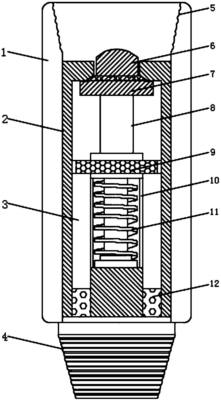
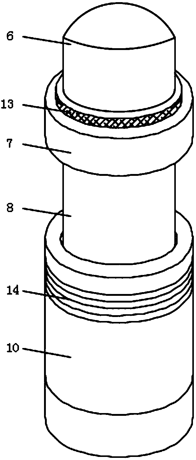
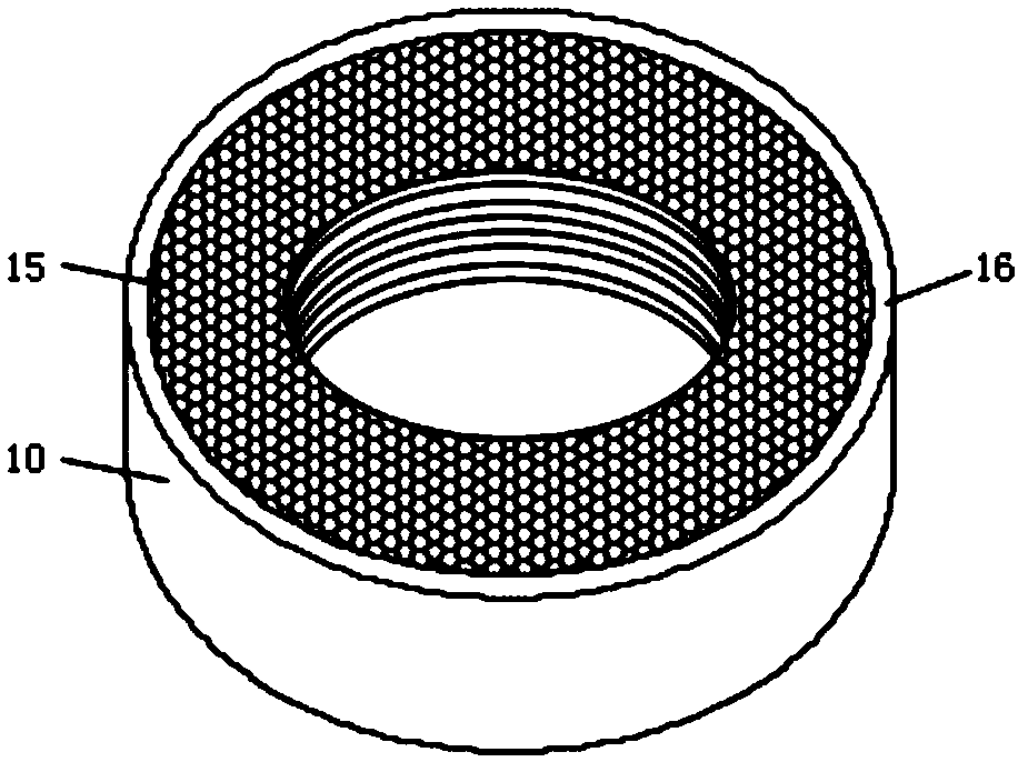
The invention discloses a drilling tool floating valve for a well control device. The drilling tool floating valve for the well control device comprises a valve body and a valve core; a valve seat isfixed on the internal side of the valve body; and the valve core is mounted in the valve seat. According to the drilling tool floating valve for the well control device, as the valve seat and the valve core are arranged on the internal side of the floating valve, the valve core arranged in the valve seat consists of a piston head, a piston rod and a spring; and therefore, when a drilling fluid flows through the valve body, the spring arranged in the valve core retracts under a hydraulic effect to move a piston downwards, a sealing state of the valve seat and the piston head can be unlocked sothat a drilling fluid flows into a cavity of the valve seat, and the drilling fluid flows more smoothly via a hollowed-out structure circulation passage formed in the bottom of the valve seat; when the drilling fluid is stopped from being conveyed, the hydraulic pressure cannot impel the spring so that the spring returns to enable the piston head and the valve seat to be locked in a matched manner; as the spring is mounted in the valve core and isolated from outside, the spring can be protected against being eroded, and the service life of the valve body can be prolonged; and through adoptionof a piston type structure, the sensitivity of the floating valve is made higher.

Description

technical field [0001] The invention relates to the technical field of blowout prevention tools in drilling tools, in particular to a drilling tool float valve for a well control device. Background technique [0002] For regional exploration wells, hydrogen sulfide-containing wells, gas wells, and wells with high gas-oil ratio, drill tools should be installed in the drilling tool assembly in time after drilling 100-150 meters before the target layer, or after drilling oil and gas layers that are not indicated in the design. Float valve, drilling tool float valve is an internal blowout prevention tool widely used in oil and gas drilling technology. According to the shape of the valve core, it is classified into arrow shape, hemispherical shape and valve plate type. [0003] During the use of the arrow-shaped drilling tool float valve, generally the internal valve core does not have corresponding protective measures, and the spring is exposed on the outside. The mud has a cert...

Claims


Application Information

Patent Timeline
Patent Type & Authority Applications(China)
IPC IPC(8): E21B21/10
CPCE21B21/10
Inventor 黄涵青
Owner 黄涵青
Why Eureka
Try Eureka