Spring-internal compression buffer oil cylinder

A buffer oil cylinder and built-in spring technology, which is applied in the hydraulic field, can solve the problems of non-cylindrical dimensions, high processing quality requirements, and high cost of welded components of the cylinder body, so as to avoid poor sealing, low manufacturing cost, and easy debugging and installation. Effect

Pending Publication Date: 2019-01-01
JINAN FUCHI TECH CO LTD
View PDF0 Cites 0 Cited by
  • Summary
  • Abstract
  • Description
  • Claims
  • Application Information

AI Technical Summary

Problems solved by technology

[0003] The disadvantages of the existing buffer device scheme are that the buffer device has concentricity, cylinder welding components have non-cylindrical and dimensional tolerance requirements, high processing quality requirements, and high cost

Method used


Image

  • Spring-internal compression buffer oil cylinder
  • Spring-internal compression buffer oil cylinder
  • Spring-internal compression buffer oil cylinder

Examples


Embodiment Construction

[0022] In order to better understand the present invention, the implementation manner of the present invention will be explained in detail below in conjunction with the accompanying drawings.

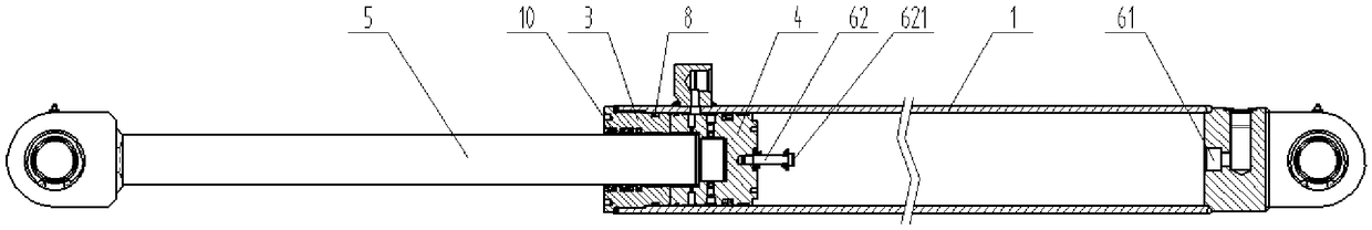
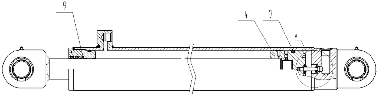
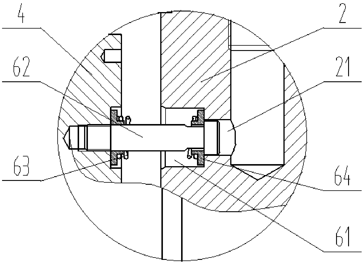
[0023] as attached figure 1 to attach Figure 5 As shown, a built-in spring compression buffer oil cylinder includes a cylinder body, a cylinder rear cover 2, a cylinder front cover 3, a piston 4, a piston rod 5 and a buffer device, and the cylinder body 1 corresponds to the cylinder rear cover 2 and the cylinder front cover 3 respectively. Connected, the piston rod 5 is located in the cylinder body 1, the piston 4 cooperates with the piston rod 5, and an oil outlet 21 is also provided in the oil cylinder rear cover 2.

[0024] The buffer device includes a stepped hole 61, a buffer rod 62, a spring 63 and two spring positioning seats 64. The head end of the buffer rod 62 is fixed at the center of the front end of the piston 4, and a cylindrical stopper 621 is provided at the end of the...


PUM


Abstract

The invention discloses a spring-internal compression buffer oil cylinder. The spring-internal compression buffer oil cylinder comprises a cylinder block, an oil cylinder back cover, an oil cylinder front cover, a piston, a piston rod and a buffer device; an oil outlet is formed in the oil cylinder back cover; the buffer device comprises a step hole, a buffer rod, a spring and two spring positioning bases; the head end of the buffer rod is fixed in the center position of the front end surface of the piston; the buffer rod is provided with a buffer groove near the tail end; the spring and the two spring positioning bases sleeve the buffer rod; the two spring positioning bases are oppositely arranged; two ends of the spring are connected with the spring positioning bases; the step hole is formed in the oil cylinder back cover; the step hole corresponds to the spring positioning bases; and an oil outlet is correspondingly connected with the step hole. The spring-internal compression buffer oil cylinder is simple and compact in structure, excellent in buffer effect of the buffer device, easy to be debugged and installed, reliable in buffer operation and low in production cost.

Description

technical field [0001] The invention relates to the field of hydraulic technology, in particular to a built-in spring compression buffer oil cylinder. Background technique [0002] A hydraulic cylinder is a hydraulic actuator that converts hydraulic energy into mechanical energy and performs linear reciprocating motion (or swing motion). It has simple structure and reliable operation. When it is used to realize reciprocating motion, the deceleration device can be eliminated, and there is no transmission gap, and the motion is stable, so it is widely used in various mechanical hydraulic systems. In the hydraulic system, the hydraulic cylinder is used to drive a mechanism with a certain quality. When the hydraulic cylinder moves to the end of the stroke, it has a large kinetic energy. If the deceleration is not performed, the hydraulic cylinder piston will mechanically collide with the cylinder head, resulting in impact and noise. Destructive, shortening the service life of ...

Claims


Application Information

Patent Timeline
Patent Type & Authority Applications(China)
IPC IPC(8): F15B15/14F15B15/22F15B15/20
CPCF15B15/14F15B15/1442F15B15/1452F15B15/1461F15B15/20F15B15/22F15B15/226
Inventor 尹延慧
Owner JINAN FUCHI TECH CO LTD
Why Eureka
Try Eureka