
Combustor head

A stove head and mixing chamber technology, which is applied to the field of kitchen gas stoves, can solve the problems of insufficient flame combustion, insufficient supply of combustion-supporting air, and flameout when sitting on a pot, so as to improve the combustion efficiency, reduce the difficulty of cleaning, and achieve the effects of sufficient gas combustion.

Active Publication Date: 2019-01-01
HANGZHOU ROBAM APPLIANCES CO LTD
View PDF17 Cites 1 Cited by
  • Summary
  • Abstract
  • Description
  • Claims
  • Application Information

AI Technical Summary

Problems solved by technology

Although this kind of burner looks more beautiful, the blockage of the secondary air supply channel by the outer ring fire cover also hinders the smooth supply of secondary air, which indirectly leads to insufficient combustion of the inner flame, and yellow flames are prone to occur, and even worse. Otherwise, the CO in the exhaust gas after combustion will exceed the standard, forming a serious safety hazard
At the same time, if the supply of combustion-supporting air is not in place, the combustion efficiency of the burner will be greatly reduced
Due to the reduction of secondary air supply, it is difficult to meet the combustion of different types of gas sources, resulting in poor adaptability of the gas source of the burner, and it is difficult to achieve good combustion conditions
[0003] In addition, due to the insufficient secondary air replenishment of the inner flame, after the pot is placed on the pot stand of the burner, it is also easy to turn off the flame while sitting on the pot, which brings a poor user experience to the household burner

Method used


Image

  • Combustor head
  • Combustor head
  • Combustor head

Examples


Embodiment 1

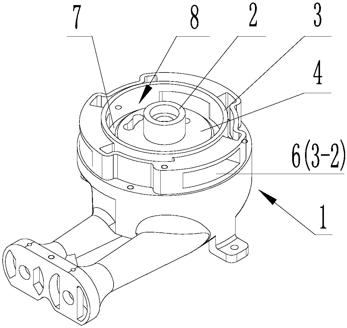
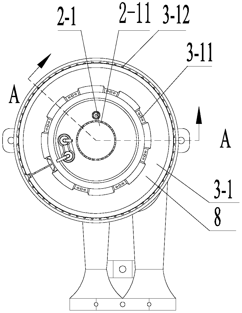
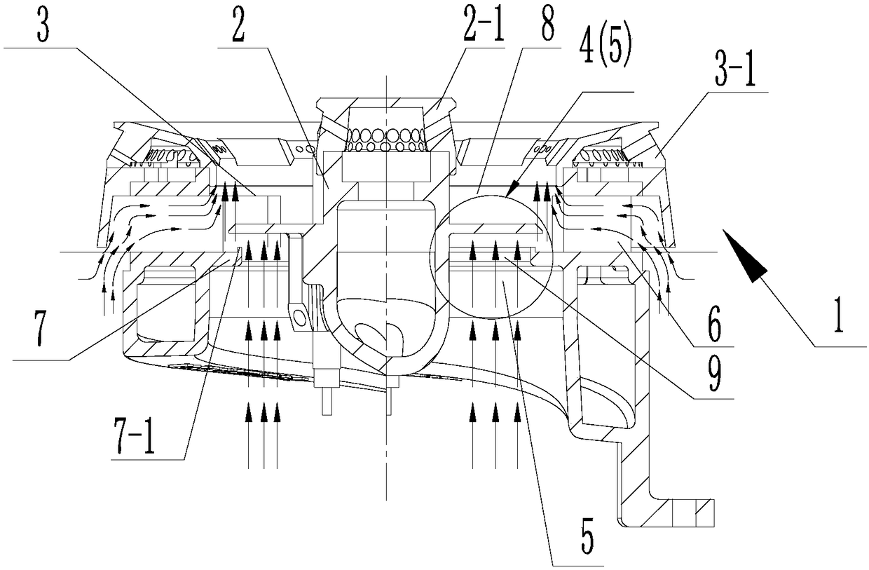
[0030] Such as figure 1 , 3 In the example of the present invention, a furnace head 1 of the present invention includes an inner ring mixing chamber 2, an outer ring mixing chamber 3 and a secondary air supplementary channel 5, and is arranged in the inner ring mixing chamber 2 and the outer ring mixing chamber 3 is suitable for the passage area 8 connected with the secondary air supplementary passage 5, and the upper bottom wall 4 and the lower bottom wall 7 are arranged at intervals below the passage area 8, and the upper bottom wall 4 and the lower bottom wall 7 are in the The projections in the vertical direction partially overlap, and an annular long hole 9 as a secondary air supplementary hole is provided in the space between the upper bottom wall 4 and the lower bottom wall 7. One end of the annular long hole 9 communicates with the passage area 8, and the other end It communicates with the atmosphere below the burner 1.

[0031] In this embodiment, the open cavity at...

Embodiment 2

[0034] Such as figure 1 , 3 In the example of the present invention, the furnace head 1 of the present invention includes an inner ring mixing chamber 2 and an outer ring mixing chamber 3, and a passage area 8 is arranged between the inner ring mixing chamber 2 and the outer ring mixing chamber 3, and the passage area 8 The upper bottom wall 4 and the lower bottom wall 7 arranged at intervals up and down are arranged below the upper bottom wall, and the interval area between the upper bottom wall 4 and the lower bottom wall 7 is provided with an annular elongated hole 9 communicating with the passage area 8 and the external atmosphere, and the annular elongated hole 9 is hidden. It is arranged directly below the upper bottom wall 4 , surrounds the inner ring mixing chamber 2 , and is arranged close to the radially outer wall of the inner ring mixing chamber 2 , and is used to supplement the secondary air required for combustion into the passage area 8 . The inner ring mixing ...


PUM


Abstract

The invention discloses a combustor head. The combustor head comprises an inner ring mixing cavity, an outer ring mixing cavity, a secondary air supplementing channel and a channel region, wherein thechannel region is arranged between the inner ring mixing cavity and the outer ring mixing cavity; a top wall and a bottom wall which are vertically arranged at intervals are arranged below the channel region; secondary air supplementing holes are formed in an interval region between the top wall and the bottom wall; and one end of each secondary air supplementing hole communicates with the channel region while the other end of the secondary air supplementing hole communicates with the atmosphere of the lower portion of the head. The atmosphere of the lower portion of the head communicates with the channel region on the upper portion of the head to form the secondary air supplementing channel of a combustor, thus, air is supplemented upwards from the lower portion of the head, multi-anglesupplementing states of combustion-supporting air of the combustor are formed, enough oxygen required for combustion is provided, thus, combustion of gas is full, the combustion efficiency of the combustor is greatly improved, meanwhile, the requirement of the high-power combustor on lots of supplemented combustion-supporting air is also met, and the combustor head lays a foundation for the designof the high-power combustor.

Description

technical field [0001] The invention relates to the field of kitchen gas stoves, in particular to a stove head of a burner. Background technique [0002] At present, the outer ring mixing cavity of the household gas stove burner is provided with a secondary air replenishment channel that connects the channel area between the inner and outer ring mixing cavity with the external atmosphere. block. Although this kind of burner looks more beautiful, the blockage of the secondary air supply channel by the outer ring fire cover also hinders the smooth supply of secondary air, which indirectly leads to insufficient combustion of the inner flame, and yellow flames are prone to occur, and even worse. Otherwise, the CO in the exhaust gas after combustion will exceed the standard, forming a serious safety hazard. At the same time, if the supply of combustion air is not in place, the combustion efficiency of the burner will be greatly reduced. Due to the reduction of secondary air su...

Claims


Application Information

Patent Timeline
Patent Type & Authority Applications(China)
IPC IPC(8): F23D14/06F23D14/46F23D14/62
CPCF23D14/06F23D14/46F23D14/62F23D2203/007Y02E20/34
Inventor 任富佳柳发威颜运宇
Owner HANGZHOU ROBAM APPLIANCES CO LTD
Learn More