Boiler flue gas waste heat recycling device

A technology of waste heat recovery and boiler flue gas, applied in the direction of reducing greenhouse gases, climate sustainability, lighting and heating equipment, etc., can solve the problems of waste of heat resources, heat loss, easy-to-burn equipment, etc., to save resources and improve Utilization rate, effect of improving heat utilization rate

Inactive Publication Date: 2019-01-01
WUHU MINGREN THERMAL ENERGY EQUIP
View PDF2 Cites 3 Cited by
  • Summary
  • Abstract
  • Description
  • Claims
  • Application Information

AI Technical Summary

Problems solved by technology

The temperature of the flue gas coming out of the chimney reaches over 300°C, direct discharge is a serious waste of heat resources, and when the high-temperature flue gas enters environmental protection equipment such as bag filter, it is easy to burn out the equipment
Existing heat recovery devices expose the water storage device directly to the outside air, which is easy to dissipate heat to the outside air, resulting in heat loss

Method used


Image

  • Boiler flue gas waste heat recycling device

Examples


Embodiment Construction

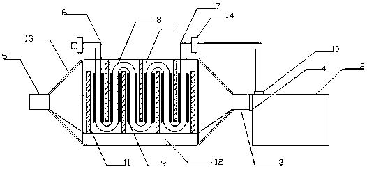
[0012] In order to deepen the understanding of the present invention, the present invention will be further described below in conjunction with examples, which are only used to explain the present invention and do not constitute a limitation to the protection scope of the present invention. Such as figure 1 As shown, this embodiment provides a boiler flue gas waste heat recovery and utilization device, including a recovery chamber 1 and a boiler 2, the recovery chamber 1 is located on the left side of the boiler 2, the right side of the recovery chamber 1 is provided with a smoke inlet pipe 3, and the boiler 2 is located on the right side. There is a smoke outlet 4 on the side, the smoke inlet pipe 3 is connected to the smoke outlet 4, the smoke outlet pipe 5 is arranged on the left side of the recovery chamber 1, the water inlet pipe 6 is arranged on the upper left side of the recovery chamber 1, and the upper right side of the recovery chamber 1 is arranged There is a water ...


PUM


Abstract

The invention provides a boiler flue gas waste heat recycling device which comprises a recycling room and a boiler. The recycling room is arranged on the left side of the boiler. A flue gas inlet pipeis arranged on the right side of the recycling room. A flue gas discharging port is formed in the right side of the boiler. The flue gas inlet pipe is connected with the flue gas discharging port. Aflue gas discharging pipe is arranged on the left side of the recycling room. A water inlet pipe is arranged above the left side of the recycling room. A water outlet pipe is arranged above the rightside of the recycling room. A curved water pipe is arranged in the recycling room. The left end of the curved water pipe is connected with the water inlet pipe, and the right end of the curved water pipe is connected with the water outlet pipe. A heat pipe is arranged on the surface of the curved water pipe. A water inlet is formed in the left top side of the boiler and is connected with the wateroutlet pipe. By means of the boiler flue gas waste heat recycling device, the heat pipe is used for absorbing and transmitting heat in flue gas into the curved water pip to heat cold water in the curved water pipe, heated water enters the boiler from the water inlet through the water outlet pipe, the working efficiency of the boiler is improved, and resources are saved.

Description

technical field [0001] The invention relates to the technical field of environmental protection equipment, in particular to a boiler flue gas waste heat recovery and utilization device. Background technique [0002] After the boiler flue gas is discharged, after the dust removal and desulfurization operations of the dust removal equipment, it will be discharged after the emission standard reaches the standard. The temperature of the flue gas coming out of the chimney reaches over 300°C. Direct discharge is a serious waste of heat resources, and when the high-temperature flue gas enters environmental protection equipment such as bag filter, it is easy to burn out the equipment. Existing heat recovery devices all expose the water storage device directly to the outside air, which is easy to dissipate heat to the outside air and cause heat loss. So it becomes very important to solve these problems. Contents of the invention [0003] The purpose of the present invention is to...

Claims


Application Information

Patent Timeline
Patent Type & Authority Applications(China)
IPC IPC(8): F23J15/06F23J15/02
CPCF23J15/025F23J15/06Y02E20/30
Inventor 洪佳佳
Owner WUHU MINGREN THERMAL ENERGY EQUIP
Why Eureka
Try Eureka