
A descaling device for a cooler

A technology for coolers and dirt, which is applied in the field of descaling devices for coolers, which can solve the problems of inconvenient control of descaling devices and less power source of descaling devices, and achieve fast and thorough descaling, which is beneficial to descaling

Active Publication Date: 2019-12-03
SUZHOU RUIPENGCHENG SCI & TECH CO LTD
View PDF1 Cites 0 Cited by
  • Summary
  • Abstract
  • Description
  • Claims
  • Application Information

AI Technical Summary

Problems solved by technology

[0004] According to the deficiencies in the prior art above, the technical problem to be solved by the present invention is to propose a descaling device for the cooler, and through the setting of the descaling device, water pump and high-pressure water pump, the power source of the descaling device is few and the descaling device is not easy to control It has the advantages of high degree of automation, good descaling effect, multiple power sources, energy saving and environmental protection

Method used


Image

  • A descaling device for a cooler
  • A descaling device for a cooler
  • A descaling device for a cooler

Examples


Embodiment 1

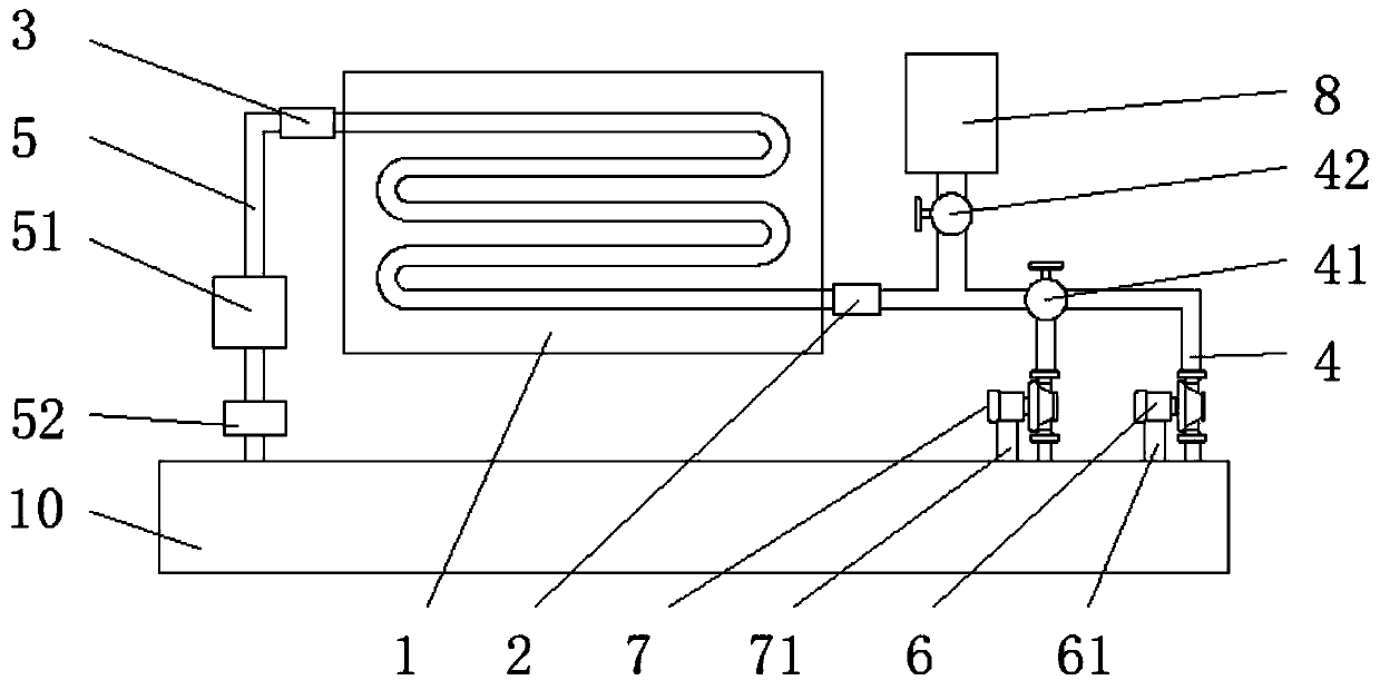
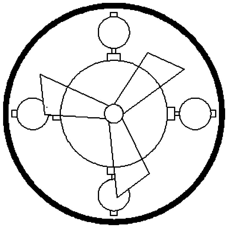
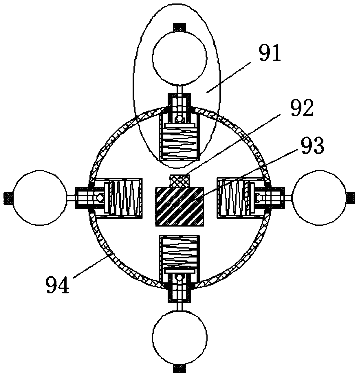
[0028] A descaling device for a cooler, comprising a cooler 1, a water inlet pipe 4, an outlet pipe 5, a high-pressure water pump 6, a water pump 7, a storage tank 8, a descaling device 9 and a water tank 10, the left end of the cooler 1 is provided with an inlet The water inlet 2, the water inlet 2 is connected with the water inlet pipe 4, the end of the water inlet pipe 4 is connected with the water outlet of the high-pressure water pump 6, the water inlet of the high-pressure water pump 6 is connected with the water tank 10, the water inlet pipe 4 is provided with a three-way valve 41, the water outlet of the water pump 7 is connected with the three-way valve 41 through the water inlet pipe 4, the water inlet of the water pump 7 is connected with the water tank 10, and the storage tank 8 is connected through the water inlet pipe 4 and the water tank 10. The water inlet 2 is connected, and the water inlet pipe 4 connected to the storage tank 8 is provided with a one-way valve...

Embodiment 2

[0039] A descaling device for a cooler, comprising a cooler 1, a water inlet pipe 4, an outlet pipe 5, a high-pressure water pump 6, a water pump 7, a storage tank 8, a descaling device 9 and a water tank 10, the left end of the cooler 1 is provided with an inlet The water inlet 2, the water inlet 2 is connected with the water inlet pipe 4, the end of the water inlet pipe 4 is connected with the water outlet of the high-pressure water pump 6, the water inlet of the high-pressure water pump 6 is connected with the water tank 10, the water inlet pipe 4 is provided with a three-way valve 41, the water outlet of the water pump 7 is connected with the three-way valve 41 through the water inlet pipe 4, the water inlet of the water pump 7 is connected with the water tank 10, and the storage tank 8 is connected through the water inlet pipe 4 and the water tank 10. The water inlet 2 is connected, and the water inlet pipe 4 connected to the storage tank 8 is provided with a one-way valve...


PUM


Abstract

The invention discloses a descaling device for a cooler. The descaling device comprises the cooler, a water input pipe, a water output pipe, a storage box, a descaling device body and a water tank. Awater inlet is formed in the left end of the cooler. The water inlet and the water input pipe are connected. A water outlet is formed in the right end of the cooler. The water outlet and the water output pipe are connected. A collecting box is connected to the water output pipe. The collecting box is connected with a dirt collecting box through the water output pipe. The dirt collecting box is arranged below the collecting box. The dirt collecting box is connected with the water tank through the water output pipe. The descaling device is arranged in the storage box. The descaling device solvesthe problems that the descaling device is few in power source and inconvenient to control, and has the advantages of being high in automation degree, good in descaling effect, much in power source and environmentally friendly, and saving energy.

Description

technical field [0001] The invention belongs to the technical field of pipeline descaling, and in particular relates to a descaling device for a cooler. Background technique [0002] A cooler is a type of heat exchange device used to cool a fluid. Usually water or air is used as coolant to remove heat. Most of the coolers contain calcium, magnesium ions and acid carbonates because of the cooling water. Carbonates are formed when cooling water flows over metal surfaces. In addition, the oxygen dissolved in the cooling water can also cause metal corrosion and form rust. Due to the generation of rust, the heat exchange effect is reduced. In serious cases, cooling water has to be sprayed outside the shell. For a long time, traditional cleaning methods such as mechanical methods (scraping and brushing) will not completely remove scale and other deposits. Chemical cleaning (pickling) etc. will cause acid to corrode the equipment and form loopholes when cleaning the equipment. ...

Claims


Application Information

Patent Timeline
Patent Type & Authority Patents(China)
IPC IPC(8): F28G1/12F28G15/00
CPCF28G1/12F28G15/00
Inventor 张高
Owner SUZHOU RUIPENGCHENG SCI & TECH CO LTD
Learn More