Unlock instant, AI-driven research and patent intelligence for your innovation.

Digital storage oscilloscope with functions of high-speed serial protocol triggering and decoding

A high-speed serial and digital storage technology, applied in digital variable display, digital variable/waveform display, instrument, etc., can solve the problem of increasing hardware cost and achieve the effect of saving hardware cost

Inactive Publication Date: 2019-01-01
UNIV OF ELECTRONIC SCI & TECH OF CHINA
View PDF2 Cites 2 Cited by
  • Summary
  • Abstract
  • Description
  • Claims
  • Application Information

AI Technical Summary

Problems solved by technology

Although these methods solve the problem of protocol decoding / triggering for high-speed serial signals, they all increase hardware costs

Method used


Image

  • Digital storage oscilloscope with functions of high-speed serial protocol triggering and decoding
  • Digital storage oscilloscope with functions of high-speed serial protocol triggering and decoding
  • Digital storage oscilloscope with functions of high-speed serial protocol triggering and decoding

Examples


Embodiment

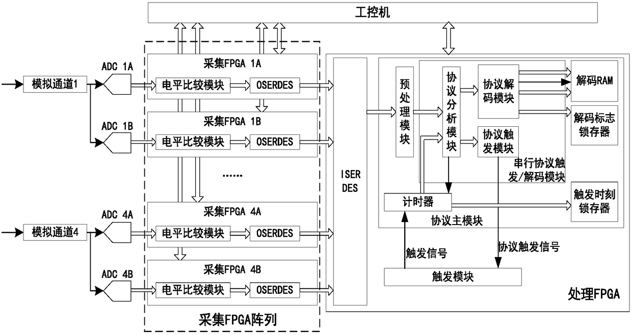
[0024] figure 1 It is a principle diagram of a specific embodiment of the digital oscilloscope with high-speed serial protocol triggering and decoding functions of the present invention.

[0025] In this example, if figure 1 As shown, the present invention has a digital storage oscilloscope with high-speed serial protocol triggering and decoding functions, including signal conditioning channels, analog-to-digital converters, control modules, waveform data storage, microprocessors, and display screens in the prior art. The acquisition, storage, and display of serial protocol signal waveforms are the same as those of ordinary digital oscilloscopes, and will not be repeated here. In order to realize the triggering and decoding functions of the high-speed serial protocol by hardware, an acquisition FPGA array and a processing FPGA are also designed in the present invention.

[0026] Such as figure 1 As shown, for simplicity, figure 1 Only the case of a single serial protocol a...

example

[0064] Taking the realization of the protocol triggering / decoding function of PCI-Express 1.0 as an example, the specific implementation of the present invention will be described in detail below.

[0065] PCIe is a high-speed serial computer expansion bus standard. It belongs to high-speed serial point-to-point dual-channel high-bandwidth transmission. The connected devices have exclusive channel bandwidth and do not share bus bandwidth. It mainly supports active power management, error reporting, and end-to-end reliability. Transmission, hot plugging, and quality of service (QOS) functions. Its main advantage is high data transfer rate, the PCI-Express 1.0 signal rate in this embodiment is 2.5Gb / s.

[0066] Table 1 is the TLP frame format;

[0067] STP

ID

TLP Header

Date payload

ECRC

LCRC

END

1Byte

2Bytes

3 / 4DW

0~1024DW

1DW

1DW

1Byte

[0068] Table 1

[0069] The TLP frame of PCI-E follows the frame form...


PUM


Abstract

The invention discloses a digital storage oscilloscope with the functions of high-speed serial protocol triggering and decoding. A multi-chip ADC performs the high-speed serial signal sampling, and then a corresponding collection FPGA performs the slowing-down and preprocessing of the sampling signal, and then finally the sampling signal is inputted into one FPGA for completing the triggering anddecoding of a high-speed serial protocol. Therefore, on the one hand, the digital storage oscilloscope can meet the triggering / decoding real-time performance of the high-speed serial protocol and improve the function requirements of the positioning accuracy of a triggering point, and also can support the triggering and decoding of multiple types of protocols, such as RS232, PCIE, D-PHY, and Ethernet; on the other hand, a hardware circuit structure referred in the whole scheme is consistent with the structure of the time alternating sampling technology which is widely used in a digital oscilloscope, thereby saving the hardware cost.

Description

technical field [0001] The invention belongs to the technical field of digital oscilloscopes, and more specifically relates to a digital storage oscilloscope with high-speed serial protocol triggering and decoding functions. Background technique [0002] At present, with the development of electronic technology, the application range of serial bus has been greatly expanded, such as data transmission in medical image analysis equipment, communication between smart phones and their cameras, and multi-channel real-time control in industrial systems. At the same time, the serial bus signal rate used is getting faster and faster, such as PCIe, USB 3.0, SATA and other commonly used bus signal rates are above 1Gb / s, which puts forward higher requirements for the serial protocol decoding / triggering function of digital oscilloscopes. requirements. However, as serial buses are increasingly used in embedded system designs instead of wide parallel buses, designers place higher demands ...

Claims


Application Information

Patent Timeline
IPC IPC(8): G01R13/02
CPCG01R13/0209G01R13/0218G01R13/0254
Inventor 杨扩军周镱张沁川叶芃邱渡裕
Owner UNIV OF ELECTRONIC SCI & TECH OF CHINA
Features
  • R&D
  • Intellectual Property
  • Life Sciences
  • Materials
  • Tech Scout
  • Unparalleled Data Quality
  • Higher Quality Content
  • 60% Fewer Hallucinations
Learn More