An isolated BUCK-BOOST circuit and control method thereof

A technology of circuits and isolation transformers, which is applied in the direction of control/regulation systems, electrical components, and regulation of electrical variables, and can solve problems such as the inapplicability of BUCK-BOOST circuits

Pending Publication Date: 2019-01-01
ZTE CORP
View PDF7 Cites 5 Cited by
  • Summary
  • Abstract
  • Description
  • Claims
  • Application Information

AI Technical Summary

Problems solved by technology

However, for occasions with electrical isolation requirements, due to the wide input voltage range of the isolated intermediate bus power supply, therefore, figure 1 The BUCK-BOOST circuit shown is not applicable

Method used


Image

  • An isolated BUCK-BOOST circuit and control method thereof
  • An isolated BUCK-BOOST circuit and control method thereof
  • An isolated BUCK-BOOST circuit and control method thereof

Examples


Embodiment Construction

[0048] In order to make the purpose, technical solution and advantages of the present invention more clear, the embodiments of the present invention will be described in detail below in conjunction with the accompanying drawings. It should be noted that, in the case of no conflict, the embodiments in the present application and the features in the embodiments can be combined arbitrarily with each other.

[0049] The steps shown in the flowcharts of the figures may be performed in a computer system, such as a set of computer-executable instructions. Also, although a logical order is shown in the flowcharts, in some cases the steps shown or described may be performed in an order different from that shown or described herein.

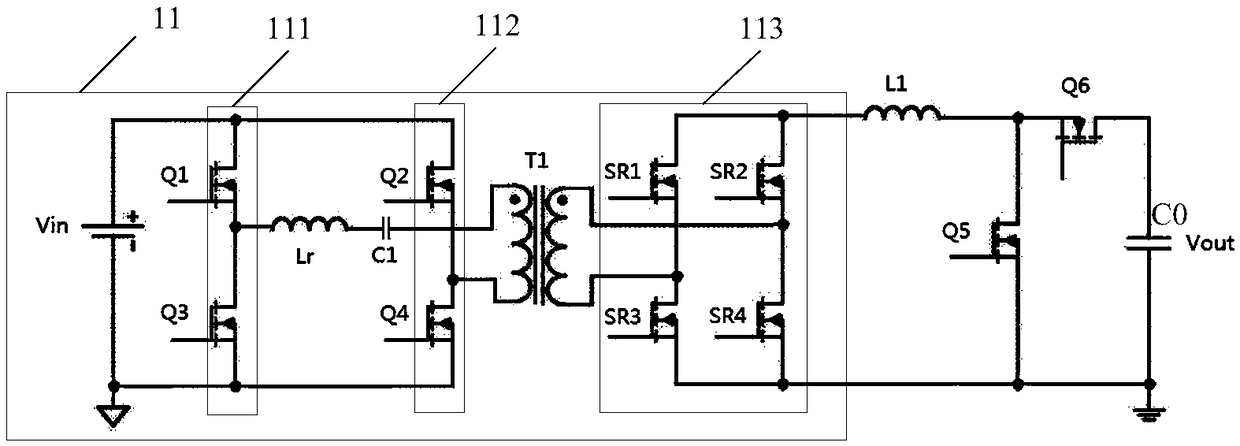
[0050] see figure 2 , an embodiment of the present invention provides an isolated BUCK-BOOST circuit, including:

[0051] A phase-shifted full-bridge conversion unit 11 using transformer isolation;

[0052] Switch tube Q5;

[0053] Rectifier tube Q6; ...


PUM


Abstract

The invention discloses an isolated BUCK-BOOST circuit and a control method thereof. The circuit includes a phase-shifted full-bridge transform unit with transformer isolation, a switch tube, a rectifying tube, a first inductor and an output capacitor; in the two output ends of the phase-shifted full-bridge transform unit, one is connected to one end of the first inductor, and the other one and one end of the switch tube are connected to one end of the output capacitor; the other end of the first inductor and the other end of the switch tube are connected to one end of the rectifying tube, andthe other end of the rectifying tube is connected to the other end of the output capacitor; the input end of the phase-shifted full-bridge transform unit is taken as the input voltage end of the isolated BUCK-BOOST circuit; and the output capacitor is taken as the output voltage end of the isolated BUCK-BOOST circuit. The isolated BUCK-BOOST circuit can suitable for wide input voltage ranges andmeet electrical isolation requirements.

Description

technical field [0001] The invention relates to the technical field of power electronics, in particular to an isolated BUCK-BOOST circuit and a control method thereof. Background technique [0002] In the field of power electronics technology, especially DC / DC converters, such as figure 1 The shown BUCK-BOOST circuit maintains higher efficiency over a wider input voltage range than either the BUCK circuit or the BOOST circuit over the entire input voltage range. therefore, figure 1 The buck-boost circuit shown is widely used in non-isolated applications. However, for occasions with electrical isolation requirements, due to the wide input voltage range of the isolated intermediate bus power supply, therefore, figure 1 The BUCK-BOOST circuit shown is not applicable. Therefore, there is a need for a BUCK-BOOST circuit that is suitable for a wide input voltage range and meets electrical isolation requirements. Contents of the invention [0003] In order to solve the above...

Claims


Application Information

Patent Timeline
Patent Type & Authority Applications(China)
IPC IPC(8): H02M3/335
CPCH02M3/33592H02M1/007
Inventor 胡永辉
Owner ZTE CORP
Why Eureka
Try Eureka