Single-chip pararrel isolation amplifier

An isolated amplifier and single-chip technology, applied in the direction of transistors, etc., can solve problems such as interference and affecting the sensitivity of parallel optical receivers

Inactive Publication Date: 2005-12-21
SOUTHEAST UNIV
View PDF0 Cites 0 Cited by
  • Summary
  • Abstract
  • Description
  • Claims
  • Application Information

AI Technical Summary

Problems solved by technology

All optical receiving amplifiers of the CMOS process parallel optical receiver share the same silicon substrate, and the signal of any optical receiving amplifier can be coupled into other optical receiving amplifiers through the substrate and cause interference to them, thereby affecting the sensitivity of the parallel optical receiver

Method used


Image

  • Single-chip pararrel isolation amplifier

Examples


Embodiment Construction

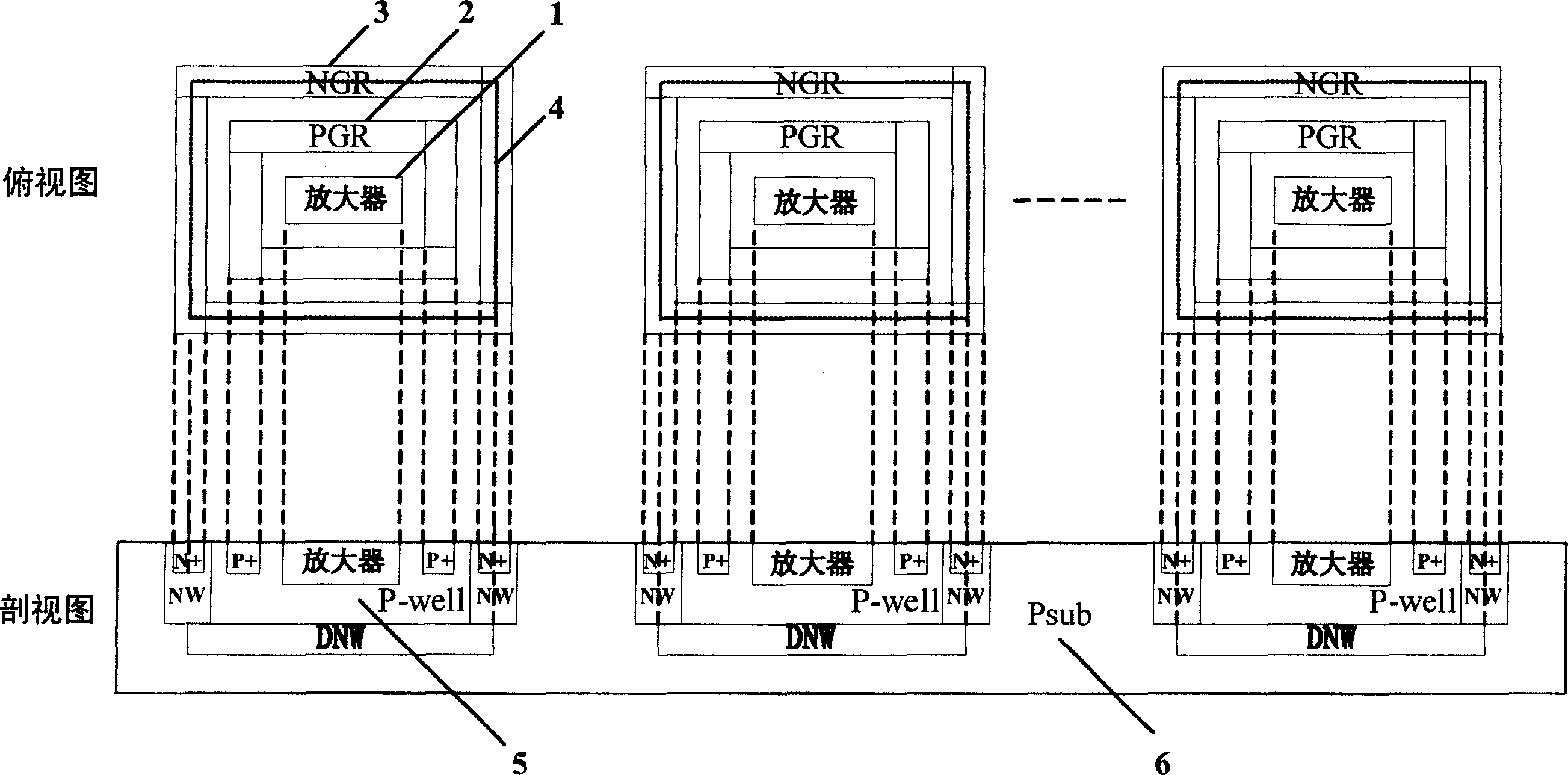
[0009] A single-chip parallel isolation amplifier for a parallel optical fiber communication system, comprising a P-type substrate 6, at least two amplifiers 1 are arranged on the P-type substrate 6, that is, two amplifiers 1 can be set on the P-type substrate 6 at the same time One, 3, 5, 6 or more amplifiers, on the P-type substrate 6 are provided with N-type regions corresponding to the number of amplifiers 1, in the N-type region is provided with a P well 5, in the P well 5 A highly doped P region is provided inside, and the highly doped P region is connected to the metal inner ring 2 through a contact hole. There is a highly doped N region, the highly doped N region is connected to the metal outer ring 3 through the contact hole and the metal inner ring 2 is located inside the metal outer ring 3, the N-type region can be a complete relatively deep and large The overall N-type region can also be composed of two or more relatively small N-type regions. For example: in this ...


PUM


Abstract

The disclosed isolated amplifier in use for parallel optical fiber communication system includes following parts and structures: at least two amplifiers are setup at P type substrate; N type regions in quantity of number equal to corresponding number of amplifier are set up at P type substrate; setting up P trap inside N type region, and setting up high adulterated P region inside P trap; through contact hole, the high adulterated P region is connected to metal inner ring, and amplifier is positioned at inner region enclosed by metal inner ring; setting up high adulterated N region at N region outside P trap, and through contact hole, the high adulterated N region is connected to metal outer ring. Features are: simple designed CMOS technique, and satisfied isolation between amplifiers.

Description

technical field [0001] The invention is a single-chip parallel amplifier that can be isolated from each other, in particular to a single-chip parallel isolation amplifier used in a parallel optical fiber communication system. Background technique [0002] With the rapid development of telecommunication network and data communication technology, optical fiber communication network has been widely used, and the continuously increasing communication speed puts forward higher and higher requirements for the data transmission rate of optical fiber communication system. Since the parallel optical fiber transmission system adopts a multi-channel parallel structure to transmit multiple channels of data at the same time, the data transmission rate of the system is greatly improved, and it is one of the main development directions of the optical fiber communication system. The parallel optical receiver is located at the front end of the parallel optical fiber communication system and ...

Claims


Application Information

Patent Timeline
Patent Type & Authority Applications(China)
IPC IPC(8): H01L27/092
Inventor 李智群薛兆丰郑锐王志功
Owner SOUTHEAST UNIV
Why Eureka
Try Eureka