
Motor control system

A motor control and controller technology, applied in control systems, AC motor control, electric vehicles, etc., can solve the problems of efficiency reduction, expansion of operating range, limited speed effect, etc.

Inactive Publication Date: 2019-01-01
DELTA ELECTRONICS INC
View PDF5 Cites 2 Cited by
  • Summary
  • Abstract
  • Description
  • Claims
  • Application Information

AI Technical Summary

Problems solved by technology

In this regard, the general existing solution is to reduce the counter electromotive force by means of field weakening, thereby increasing the upper limit of the speed. However, when using this method, additional current is required to generate the magnetic flux required for field weakening, resulting in a decrease in efficiency, and The effect of increasing the speed in this way is limited, and in the end, the operating range has not been greatly expanded

Method used


Image

  • Motor control system
  • Motor control system
  • Motor control system

Examples


Embodiment Construction

[0053] The preferred embodiments of the present invention are described below with reference to the drawings. The foregoing and other technical content, features and effects of the present invention are described in the following detailed description of a preferred embodiment with reference to the drawings. The directional terms mentioned in the following embodiments, such as: up, down, left, right, front or back, etc., are only directions with reference to the attached drawings. Accordingly, the directional terms are used to illustrate and not to limit the invention.

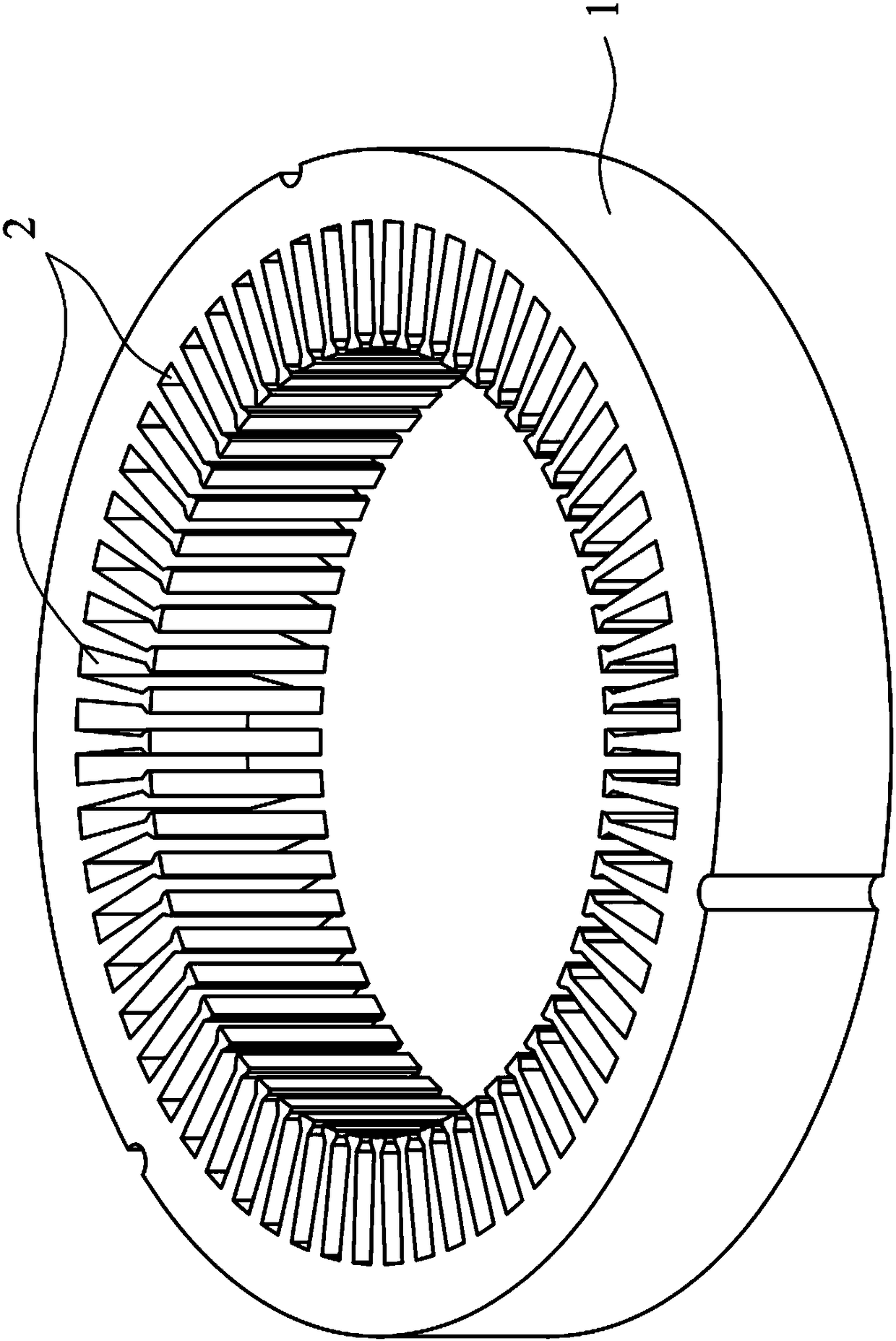
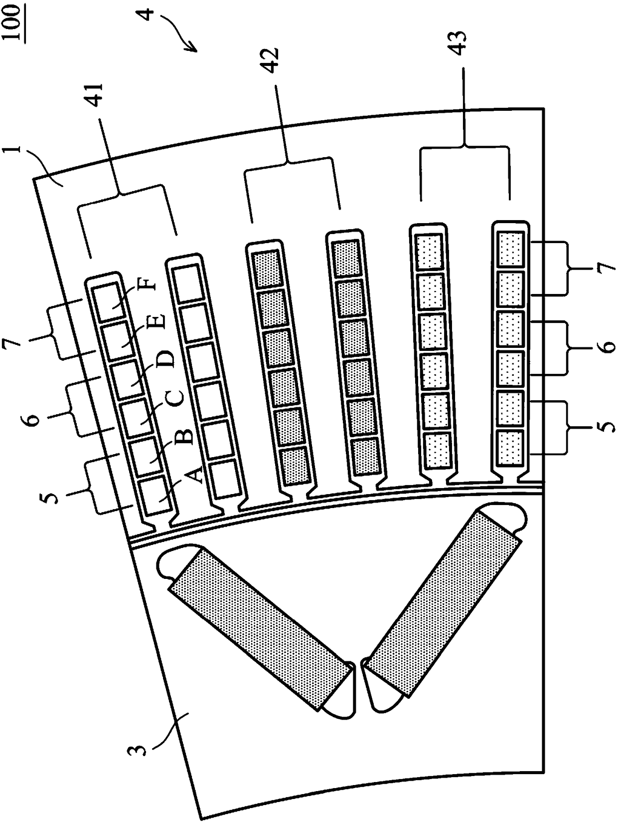
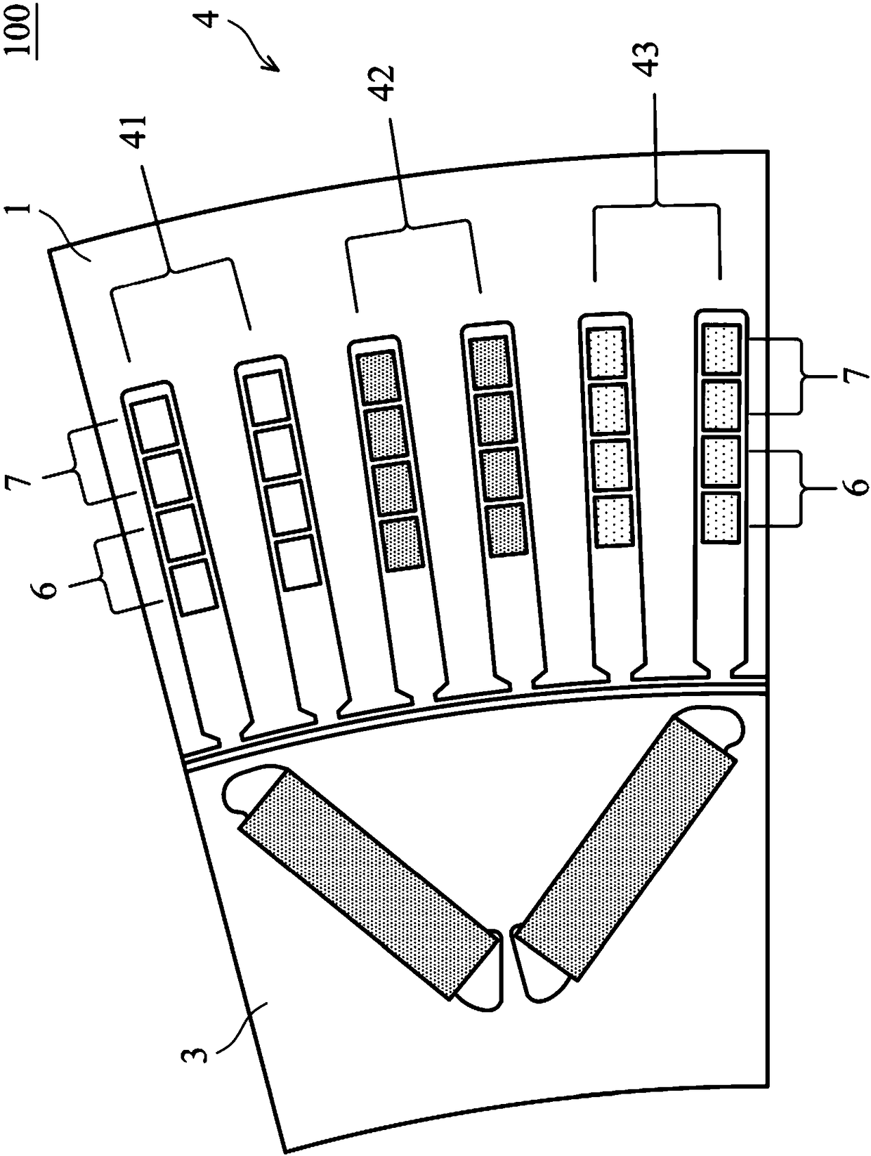
[0054] refer to Figure 7-9 , the motor control system of an embodiment of the present invention can control the conductance of the motor winding, including an electric motor 100 and a frequency converter 9, and the electric motor 100 includes a stator 1 and a rotor 3 (shown in figure 2 , 3 ). figure 1 The stator of the electric motor 100 is shown, the stator 1 is a hollow annular iron core, and a pluralit...


PUM


Abstract

The invention discloses a motor control system capable of controlling the conductance flux of motor windings. The system includes an electric motor and a frequency converter; the electric motor includes a stator, a rotor and a winding structure; the stator has an iron core forming multiple grooves; the rotor is surrounded by the stator; the winding structure is formed by inserting pins of multiplehairpin leads into the grooves; the pins are sequentially configured to multilayer leads along a direction of the stator radius in each groove; the winding structure has multiple phases, and each phase has multiple windings; the frequency converter is connected to a power supply and the windings, and has a lead changing controller which can control the conduction of the windings of each phase; and when the electric motor is in a high rotating speed mode, the conductance flux of the windings of each phase controlled by the lead changing controller controls is decreased by 1 / 3 compared with thetotal conduction of each phase.

Description

technical field [0001] The present invention relates to a motor control system capable of controlling the conductance of a motor winding, and more particularly to a motor control system for controlling an electric motor of a vehicle. Background technique [0002] In recent years, more and more vehicles have used electric motor control systems. The electric motors in the motor control system generally have a stator and a rotor. Each slot of the stator is inserted with multiple sets of copper wires with the same cross-sectional area. To form a winding, the copper wire in the slot passes a multi-phase current and generates a rotating magnetic field, thereby generating an electromotive force to rotate the rotor. As the speed of the rotor increases, the back electromotive force in the electric motor will gradually increase. Since the number of turns of the winding is fixed, there will be a problem that the speed cannot be increased after the back electromotive force conflicts wit...

Claims


Application Information

Patent Timeline
Patent Type & Authority Applications(China)
IPC IPC(8): H02P25/18
CPCH02P25/18Y02T10/64
Inventor 许宏成赖建宇蔡逸文
Owner DELTA ELECTRONICS INC
Learn More