A plastic pipe surface spraying device

A technology of surface spraying and plastic pipes, applied in spraying devices, pipeline protection, pipeline anti-corrosion/anti-rust protection, etc., can solve the problems of difficult to control paint thickness, low spraying efficiency, slow paint solidification, etc., to improve spraying efficiency. speed, meet market demand, and ensure the effect of integrity

Active Publication Date: 2021-03-12
山东陆宇塑胶有限公司
View PDF11 Cites 0 Cited by
  • Summary
  • Abstract
  • Description
  • Claims
  • Application Information

AI Technical Summary

Problems solved by technology

[0002] Plastic pipes are generally made of synthetic resin, that is, polyester, with the addition of stabilizers, lubricants, plasticizers, etc., and are extruded in the pipe making machine by the "plastic" method; they are mainly used for housing construction. Water supply system piping, drainage, exhaust and sewage sanitary pipes, underground drainage pipe systems, rainwater pipes, and threading pipes for wire installation, etc.; to increase the corrosion resistance and anti-sunshine ability of plastic pipes, or to increase the appearance of plastic pipes. , the surface of the plastic pipe needs to be sprayed; however, the existing spraying device can only spray the plastic pipe one by one, the spraying efficiency is low, the paint solidifies slowly after the plastic pipe is sprayed, and the material receiving device directly contacts the plastic just after spraying. It is easy to stain the paint, which affects the appearance of the plastic pipe after spraying, and the spraying of the existing technology is uneven, it is difficult to control the thickness of the paint, and it cannot meet the actual needs, so we invented a plastic pipe surface spraying device

Method used


Image

  • A plastic pipe surface spraying device
  • A plastic pipe surface spraying device
  • A plastic pipe surface spraying device

Examples


Embodiment Construction

[0014] In order to make the purpose, technical solutions and advantages of the embodiments of the present invention clearer, the technical solutions in the embodiments of the present invention will be clearly and completely described below in conjunction with the drawings in the embodiments of the present invention. Obviously, the described embodiments It is a part of embodiments of the present invention, but not all embodiments. Based on the embodiments of the present invention, all other embodiments obtained by persons of ordinary skill in the art without creative efforts fall within the protection scope of the present invention.

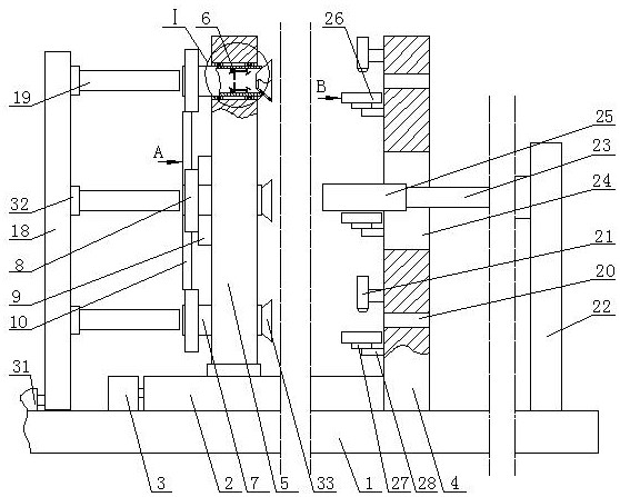
[0015]A plastic pipe surface spraying device, as shown in the figure, includes a base 1, the top side of the base 1 is fixedly installed with a horizontal horizontal moving device 2, and the left end of the power shaft of the horizontal moving device 2 is fixedly connected to the right end of the rotating shaft of the first motor 3, The positive a...


PUM


Abstract

A plastic pipe surface spraying device, including a base, a horizontal horizontal movement device is fixedly installed on the top side of the base, the left end of the power shaft of the horizontal movement device is fixedly connected to the right end of the first motor shaft, and the right side of the top side of the base is fixedly connected to a support plate The bottom side of the mobile platform of the horizontal moving device is fixedly connected to the bottom side of the movable plate, and the right side of the movable plate is uniformly opened with several first through holes distributed in a circle, and the first through holes are installed with horizontal tubes and horizontal tubes respectively. The ring gear is fixedly installed on the left end of the pipe periphery respectively, the second motor is fixedly installed on the left side of the movable plate, and the gear is fixedly installed on the left end of the second motor rotating shaft. The invention has a simple structure, can spray multiple plastic tubes at the same time, greatly improves the rate of spraying, completes the spraying of the outer circumference of the plastic tubes through the rotation and movement of the plastic tubes itself, and avoids the deviation when the plastic tubes move and the deviation when the spray gun rotates. Shifting interactions increase spraying errors.

Description

technical field [0001] The invention belongs to the field of spraying devices, in particular to a plastic pipe surface spraying device. Background technique [0002] Plastic pipes are generally made of synthetic resin, that is, polyester, with the addition of stabilizers, lubricants, plasticizers, etc., and are extruded in the pipe making machine by the "plastic" method; they are mainly used for housing construction. Water supply system piping, drainage, exhaust and sewage sanitary pipes, underground drainage pipe systems, rainwater pipes, and threading pipes for wire installation, etc.; to increase the corrosion resistance and anti-sunshine ability of plastic pipes, or to increase the appearance of plastic pipes. , the surface of the plastic pipe needs to be sprayed; however, the existing spraying device can only spray the plastic pipe one by one, the spraying efficiency is low, the paint solidifies slowly after the plastic pipe is sprayed, and the material receiving device...

Claims


Application Information

Patent Timeline
Patent Type & Authority Patents(China)
IPC IPC(8): B05B13/02
CPCB05B13/00B05B15/60B05B13/0228B05B13/025B05B13/0214F16L58/02
Inventor 宋建清王天金王秀丽李敏王英吴敏敏曹光亮李月笑
Owner 山东陆宇塑胶有限公司
Why Eureka
Try Eureka