
Dust suction type road cutting machine

A cutting machine and dust-absorbing technology, which is applied in the field of dust-absorbing road cutting machines, can solve the problems of limited dust-absorbing capacity of the cutting machine, reducing the service life of the cutting machine, and blocking the movement of the cutting machine, so as to achieve a complete and perfect overall structure of the equipment, Prevents damage to equipment and improves dust collection performance

Inactive Publication Date: 2019-01-04
徐江
View PDF0 Cites 4 Cited by
  • Summary
  • Abstract
  • Description
  • Claims
  • Application Information

AI Technical Summary

Problems solved by technology

[0004] The purpose of the present invention is to provide a dust-absorbing road cutting machine, to solve the problem that the modern road cutting machine proposed in the above-mentioned background technology often produces dust at the passing place of the road cutting machine due to the influence of the cutting operation during actual operation. There are a lot of chips. If these chips are not cleaned up in time, it will easily cause the problem that the action of the cutting machine will be blocked. Although we have initially owned a cutting machine with a dust suction function, the dust suction capacity of the cutting machine is limited. Large stones and debris can easily block the suction port or dust outlet, which has a great impact on the actual work of the cutting machine. At the same time, if things go on like this, it will cause great damage to the internal parts of the cutting machine The problem of greatly reducing the service life of the cutting machine

Method used


Image

  • Dust suction type road cutting machine
  • Dust suction type road cutting machine
  • Dust suction type road cutting machine

Examples


Embodiment Construction

[0028] The following will clearly and completely describe the technical solutions in the embodiments of the present invention with reference to the accompanying drawings in the embodiments of the present invention. Obviously, the described embodiments are only some, not all, embodiments of the present invention. Based on the embodiments of the present invention, all other embodiments obtained by persons of ordinary skill in the art without making creative efforts belong to the protection scope of the present invention.

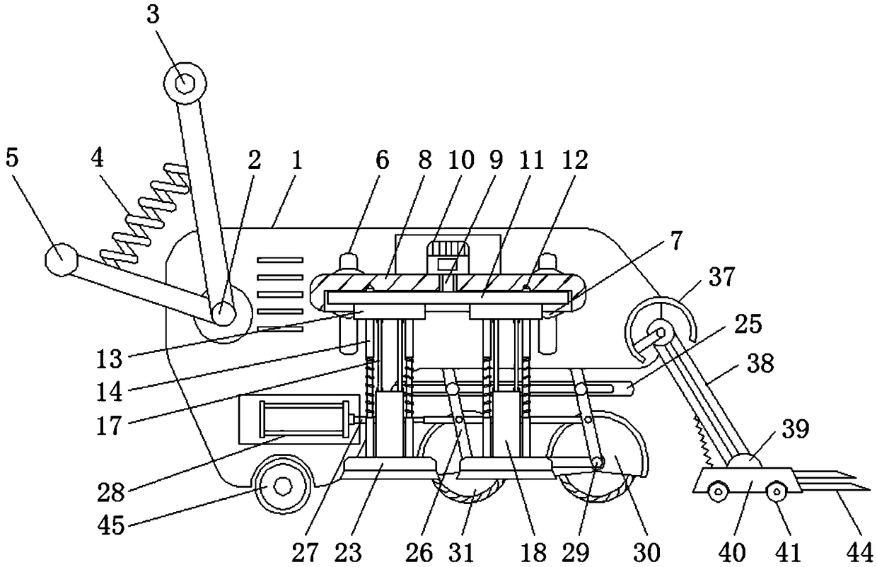
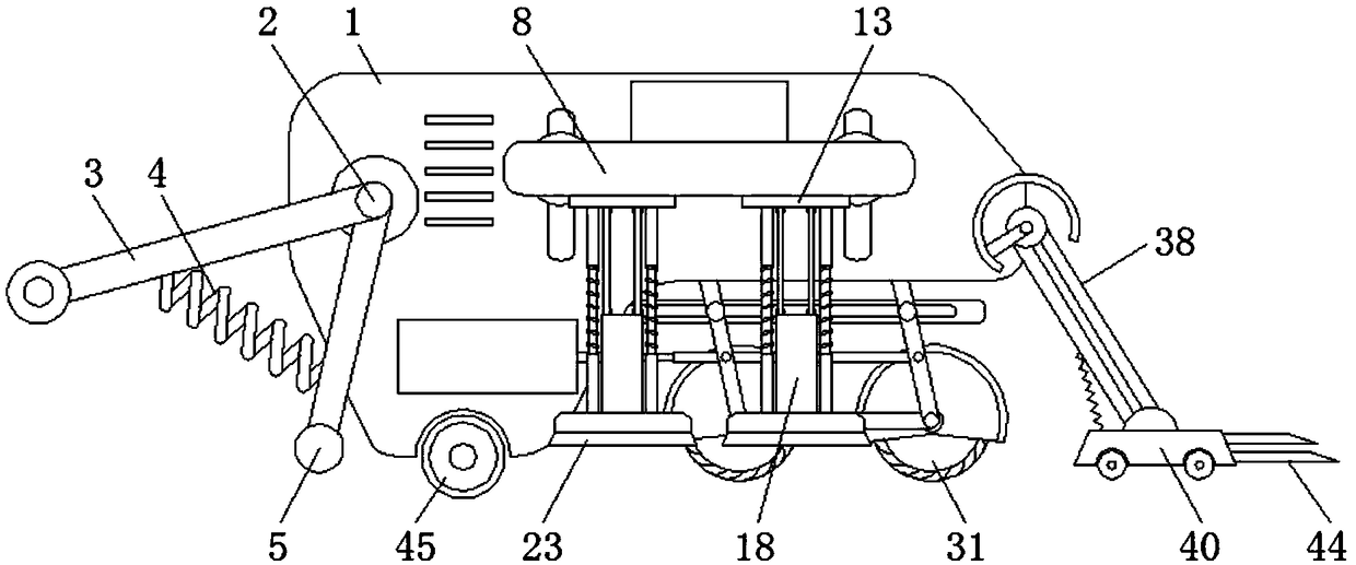
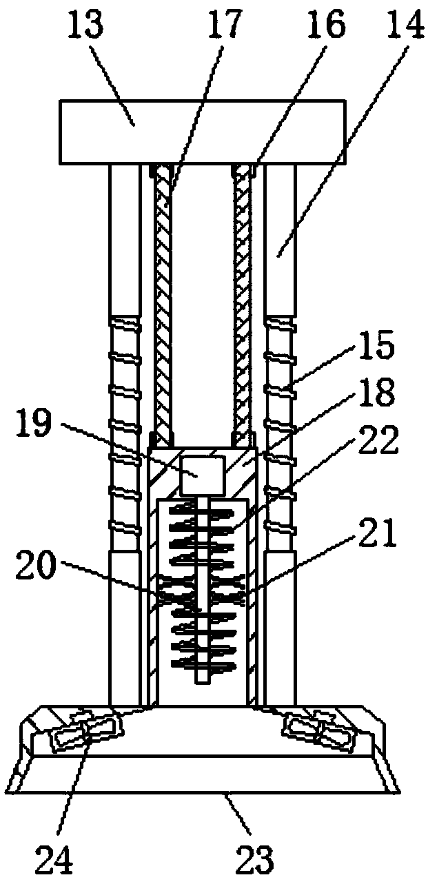
[0029] see Figure 1-7, the present invention provides a technical solution: a dust-absorbing road cutting machine, including a body 1 and a cutting disc 31, a rotating shaft 2 is installed on the upper left of the body 1, and a handle 3 is arranged above the rotating shaft 2, and the handle 3 The left side wall is fixed with a pressure spring 4, and a base rod 5 is arranged below the pressure spring 4, the handle 3 and the base rod 5 are connected to the body...


PUM


Abstract

The invention discloses a dust suction type road cutting machine. The dust suction type road cutting machine comprises a machine body and cutting knife discs; a rotation shaft is installed on the upper left portion of the machine body, a handle is arranged over the rotation shaft, a pressure spring is fixed to the left side wall of the handle, and a base rod is arranged under the pressure spring;and a support frame is installed under the machine body, supporting rods are arranged on the side wall of the support frame, a protective cover is installed on the outer side of the upper portion of each cutting knife disc, and each cutting knife disc is located on the inner side of each supporting rod. According to the dust suction type road cutting machine, the handle and the base rod both can have a good rotating structure foundation on the machine body through the rotation shaft, a good supporting structure exists between the handle and the base rod through the elastic supporting effect ofthe pressure spring, and when the equipment is idle, the base rod can be rotated downwards and finally abuts against the ground to achieve the limiting effect on the equipment; and a pressing disc isused for supporting a layer board and can move in a sliding groove, and then the position height of the whole layer board is adjusted.

Description

technical field [0001] The invention relates to the technical field of road cutting machines, in particular to a dust suction road cutting machine. Background technique [0002] Road cutting machine, also called road cutting machine, is a tool for road maintenance and construction. Its main function is to cut seams on the road surface to form a thin line with a depth of 100mm-200mm. It is often used on cement roads and asphalt roads. In the field of road construction, the use of road cutting machines is very common, and it is one of many modern mechanical equipment. In actual cutting operations, special attention should be paid to safety issues, because the cutting blades of road cutting machines have high speed and sharp edges. Failure to follow the standard actions during use may cause very serious construction accidents. [0003] Due to the influence of the cutting operation, the modern road cutting machine often produces a lot of chips when the road cutting machine pass...

Claims


Application Information

Patent Timeline
IPC IPC(8): B08B15/04B08B1/00B02C13/18E01C23/09
CPCE01C23/092B02C13/18B08B15/04B08B1/165
Inventor 徐江
Owner 徐江
Learn More