
Spring press-fit device with compound stop function

A spring press-fit, functional technology, applied in the direction of axle box installation, etc., can solve problems such as spring overload protection, and achieve the effect of improving performance and saving space

Pending Publication Date: 2019-01-04
CRRC ZIYANG CO LTD
View PDF0 Cites 4 Cited by
  • Summary
  • Abstract
  • Description
  • Claims
  • Application Information

AI Technical Summary

Problems solved by technology

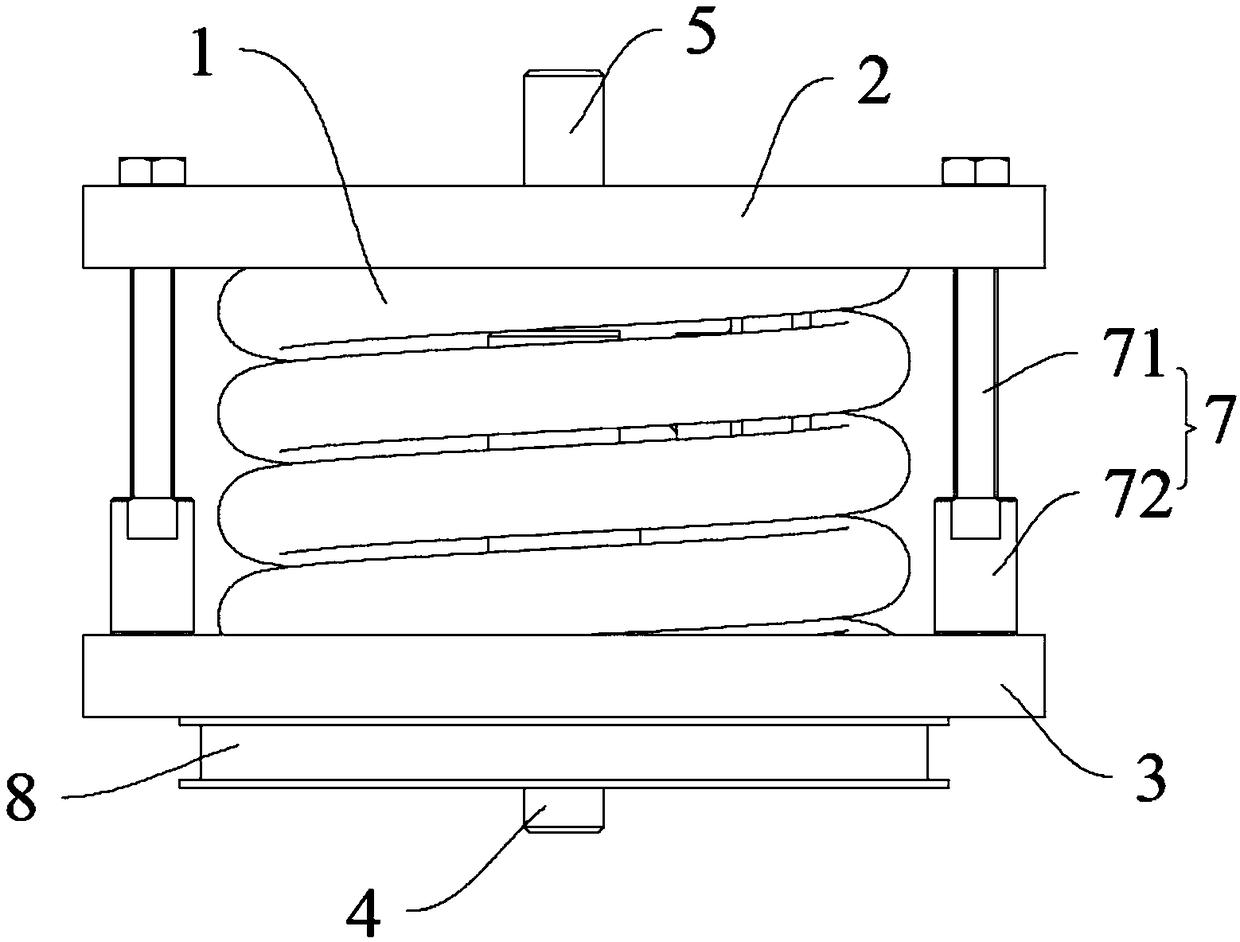
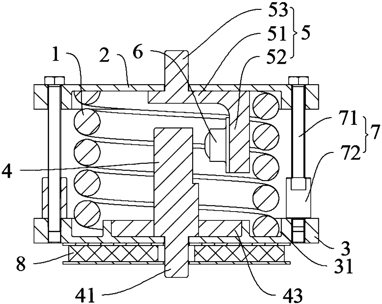
[0004] The purpose of the present invention is to provide a spring pressing device with composite stopper function in view of the above-mentioned problems in the prior art, and to solve the problem of buffer spring overload protection by setting a horizontal stopper device and a vertical stopper device. question

Method used


Image

  • Spring press-fit device with compound stop function
  • Spring press-fit device with compound stop function
  • Spring press-fit device with compound stop function

Examples


Embodiment Construction

[0025] In order to make the object, technical solution and advantages of the present invention clearer, the technology of the present invention will be further described in detail below in conjunction with the accompanying drawings and embodiments. It should be understood that the specific embodiments described here are only used to explain the present invention, not to limit the present invention.

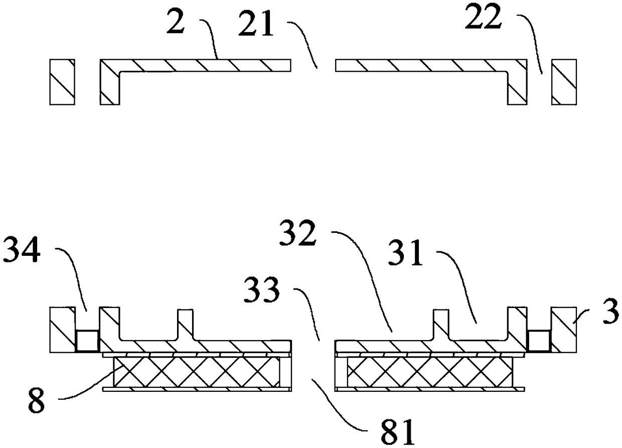
[0026] As shown in the figure, a spring pressing device with compound stop function, the pressing device includes a spring cover 2, a spring seat 3, and a buffer spring 1 between the spring cover 2 and the spring seat 3, the described The buffer spring 1 also includes a vertical stop device and a lateral stop device, which can form an effective overload protection for the buffer spring 1 when the vertical load and lateral load borne by the buffer spring 1 exceed the limit value. Moreover, the vertical stop device and the transverse stop device are arranged inside the buffer spring...


PUM


Abstract

The invention discloses a spring press-fit device with compound stopping function, characterized in that the press-fit device comprises a spring cover, a spring seat, and a cushioning spring positioned between the spring cover and the spring seat. The cushioning spring further includes a vertical stop device and a transverse stop device, and the vertical stop device and the transverse stop deviceare arranged inside the cushioning spring so as to provide effective overload protection to the cushioning spring when the vertical load and the transverse load borne by the cushion spring exceed a limit value. The structure integrates the lateral stop function and the vertical stop function into an integral arrangement inside the spring coil, thereby greatly reducing the space required for the arrangement outside the spring, making the structure of the train bogie more compact, and preventing the spring from disengaging from the safe position in the emergency state of the train.

Description

technical field [0001] The invention belongs to the technical field of locomotive bogies, in particular to a spring pressing device with compound stop function. Background technique [0002] The basic structure of the bogie is the same as that of the original empty railway bogie. Due to the change of the purpose of the train, there have been corresponding changes in the suspension device and the running wheels. The train is used to transport iron ore, and the dynamic performance index can be evaluated according to the index of the locomotive. Therefore, the first series of cone springs of the original empty iron are replaced with steel springs, and the second series of air springs are replaced with hourglass springs. Since the train runs on a small slope, in order to reduce the running resistance of the locomotive, achieve low energy consumption requirements, and increase the service life of the wheels, the original rubber running wheels of the empty railway were replaced wi...

Claims


Application Information

Patent Timeline
IPC IPC(8): B61F5/30
CPCB61F5/30
Inventor 赵素荣林丽计强任时国贾强陈清建张鸿涛曾丽周冠英石中华代世锐卢永鑫彭长福李廉枫
Owner CRRC ZIYANG CO LTD
Learn More