
High pressure well sealing oil-water well pressure punching device and punching plugging device

A technology of drilling and sealing oil under pressure, which is applied in the directions of sealing/isolation, wellbore/well components, earthwork drilling and production, etc., and can solve problems such as drilling and sealing under pressure, so as to achieve convenient operation and prevent The effect of uncontrollable pressure leakage and ensuring the safety of well sealing

Active Publication Date: 2019-01-04
王瑞东 +11
View PDF18 Cites 4 Cited by
  • Summary
  • Abstract
  • Description
  • Claims
  • Application Information

AI Technical Summary

Problems solved by technology

[0006] The purpose of the present invention is to solve the problem of opening holes under pressure and the plugging of the holes when the high-pressure liquid exists in the well of the sealed well oil and water well, and provide a kind of pressure tapping device and the hole plugging of the high pressure well sealing oil and water well device

Method used


Image

  • High pressure well sealing oil-water well pressure punching device and punching plugging device
  • High pressure well sealing oil-water well pressure punching device and punching plugging device
  • High pressure well sealing oil-water well pressure punching device and punching plugging device

Examples


Embodiment Construction

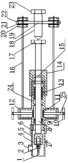
[0031] see figure 1 As shown, the high-pressure well sealing oil-water well drilling device of the present invention includes a drilling bit 1, a drill bit holder 2, a pressure relief port 3, a connecting wire head 4, a high-pressure sealing cabin body 5, a connecting clamp 6, Pressure gauge wire head 7, radial rotation rod 8, primary sealing assembly 9, hand wheel 10, sealing sheet 11, connecting ring 12, secondary sealing rubber ring 13, secondary sealing assembly 14, rubber ring gland 15, connection Screw mandrel 16, radial rotation nut 17, top screw mandrel 18, fixed plate 19, compression nut 20, stop washer 21, positioning pin hole 22, pressure force nut 23, housing 24 and rotating rod 25

[0032] The high-pressure sealed cabin body 5 is located at the front of the housing 24, and the high-pressure sealed cabin body 5 is connected to the housing 24 through the connecting clamp 6. The housing 24 is provided with a connecting ring 12, and the fixing plate 19 is located at t...


PUM


Abstract

A high pressure well sealing oil-water well pressure punching device and a punching plugging device are disclosed. The high pressure sealing cabin of the punching device is located on the front portion of a shell. The high pressure sealing cabin is connected to the shell through a connection clamp. A connecting ring sleeves the shell. A fixing plate is located on the rear portion of the shell. A connection screw rod is connected between the connecting ring and the fixing plate. The connection screw rod and the fixing plate are locked through a compression nut, a retaining washer and a positioning pin hole. The high pressure sealing cabin has a pressure release port and a pressure gauge filament head. The punching device can carry out safe and controllable punching operation. When a drill bit drills the outer wall of the oil-string casing of a high pressure oil-water well, a high pressure liquid in the well is transmitted to clean water in a high pressure control cabin, and through theprinciple of hydraulic transmission pressure, a condition is reflected to a pressure gauge and the purpose of recording pressure in the well is realized. And simultaneously, when a drilling tool is withdrawn, the clear water does not pollute an environment. The punching plugging device replaces a control valve, a problem that pressure leakage in the well can not be controlled can be effectively prevented, and the safety of well sealing in an oil field is ensured.

Description

technical field [0001] The invention relates to a device for opening holes under pressure for oil and water wells under high pressure well sealing and a hole sealing device. Background technique [0002] 1. At present, there are a large number of shut-down wells in the oilfield due to geological engineering reasons. [0003] 2. If the internal pressure cannot be detected in the original sealing technology, and the wellhead cap cannot be opened, it will cause production problems for pressure recording, near-fishing oil production increase and redevelopment, and affect the normal production of the oil field. [0004] 3. There are great potential safety hazards and environmental pollution hazards. [0005] 4. Since the pressurized hole opening device needs to install a control valve at the hole opening position, the cost of opening the hole is increased. Contents of the invention [0006] The purpose of the present invention is to solve the problem of opening holes under pr...

Claims


Application Information

Patent Timeline
Patent Type & Authority Applications(China)
IPC IPC(8): E21B33/00E21B29/00
CPCE21B29/00E21B33/00Y02E10/20
Inventor 王瑞东于守水邵立新张继路肖昶刘贵峰李肃李众田大志陆辉于源崔黎光
Owner 王瑞东
Learn More