An improved idler set device for a slag cooler

A technology of idler group and slag cooler, which is applied to mechanical equipment, rotating bearings, shafts and bearings, etc. The problem of low force limit, etc., can reduce the probability of bearing damage, increase the axial force limit, facilitate jacking up and replace the idler parts.

Active Publication Date: 2020-03-27
绍兴上虞杭协热电有限公司
View PDF5 Cites 0 Cited by
  • Summary
  • Abstract
  • Description
  • Claims
  • Application Information

AI Technical Summary

Problems solved by technology

[0004] However, in the actual operation process, after a long period of operation of the slag cooler, the height of the drum will decrease due to the wear of the support ring and the support ring, and the wear of a certain set of support rings and support rings may be large, which will cause the drum to tilt to a certain extent. Increase the axial force that the roller set needs to bear
Moreover, during the operation process, due to the influence of the working characteristics of the slag cooler, the axial movement of the drum occurs frequently, causing the axial force of the idler group to easily exceed its limit value
[0005] Since the bearings of some old-fashioned roller slag coolers are mostly deep groove ball bearings, their axial force limit is not high. When the axial force on the roller group is too large, the bearings are easily damaged and stop, resulting in Rotation failure of the drum eventually led to the outage of the slag cooler

Method used


Image

  • An improved idler set device for a slag cooler
  • An improved idler set device for a slag cooler
  • An improved idler set device for a slag cooler

Examples


Embodiment 1

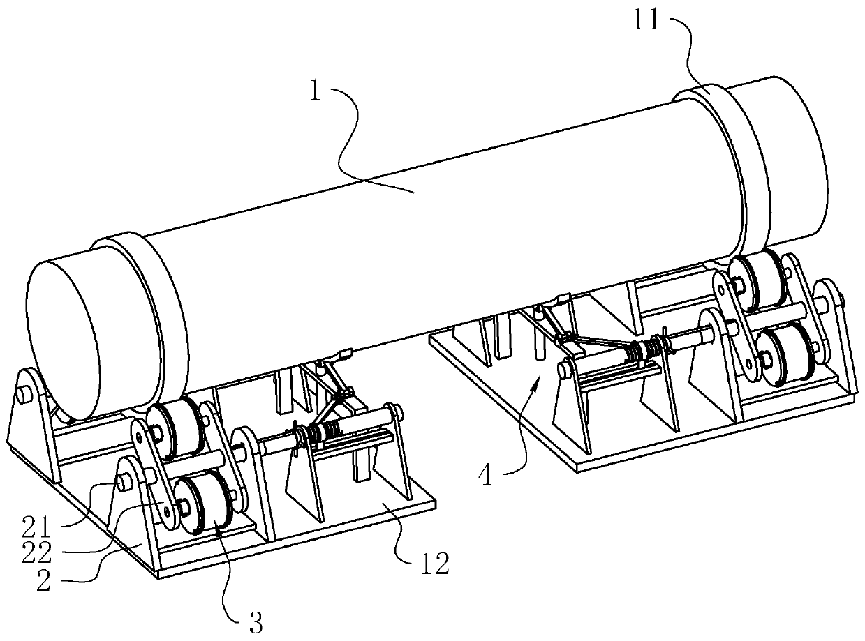
[0042] Example 1: An improved idler set device for a slag cooler, refer to figure 1 , including two bases 12, each base 12 corresponds to a support ring 11 on the drum 1. Two fixing frames 2 are fixed on the upper side of each base 12 , and the two fixing frames 2 are symmetrically located on both sides of the drum 1 along the axis of the drum 1 .

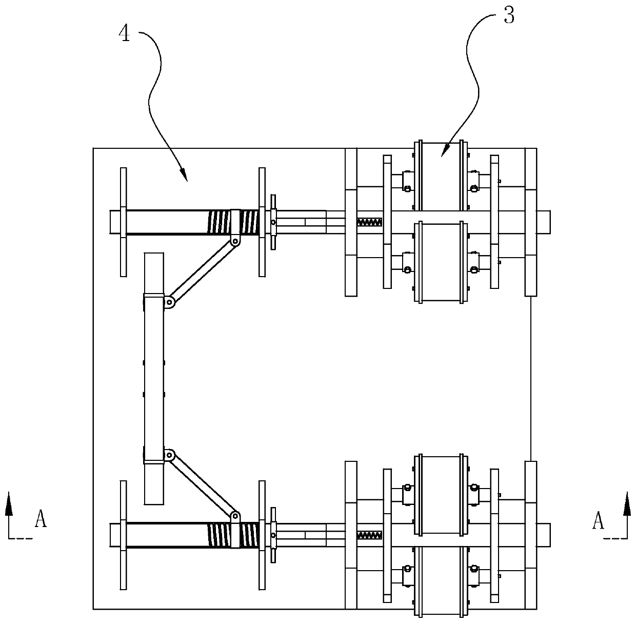
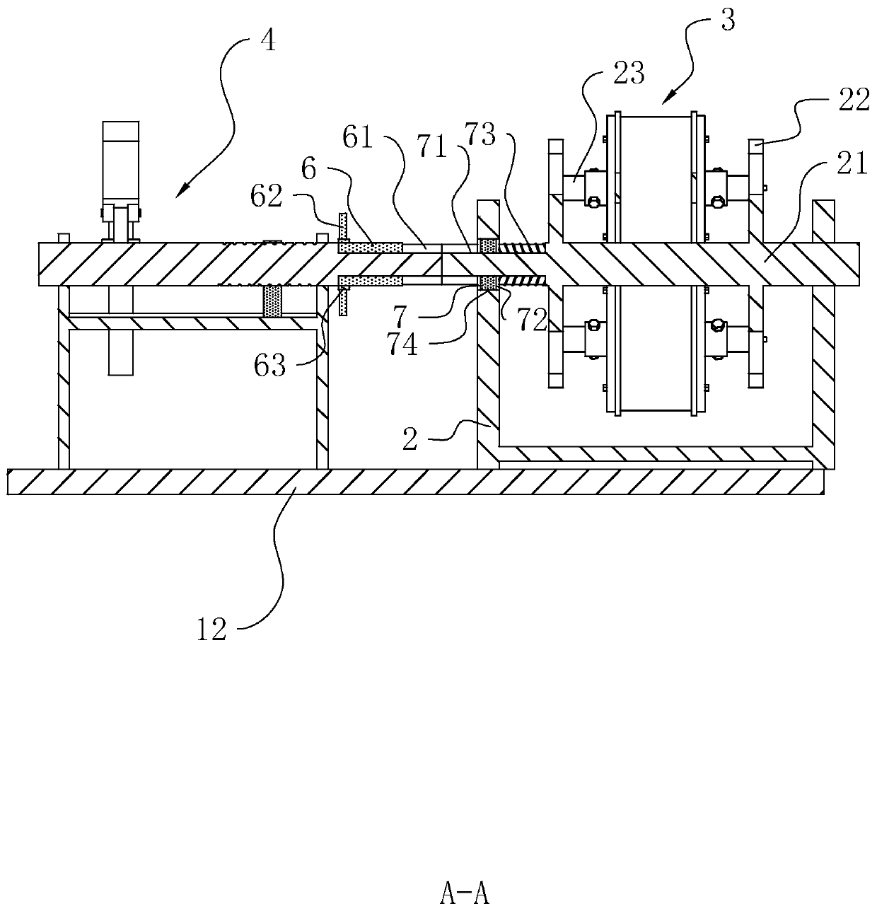
[0043] refer to Figure 4 and Figure 5 , a roller frame 22 is installed in each fixed frame 2, a main shaft 21 is fixedly worn on the roller frame 22, and two rotating holes 74 are provided on the fixed frame 2 (see image 3 ), the rotation at both ends of the main shaft 21 is embedded in the two rotations. The idler member 3 is arranged inside the idler frame 22 , and the idler member 3 can be used to abut against the support ring 11 . A rotating shaft 23 is pierced on the idler member 3 , and both ends of the rotating shaft 23 are rotatably connected to the idler frame 22 .

[0044] refer to image 3 and Figure 4 The out...

Embodiment 2

[0050] Embodiment 2, an improved idler set device for a slag cooler, refer to figure 1 , the difference from Embodiment 1 is that components such as the jacking assembly 4 are added.

[0051] refer to figure 1 , there are two idler elements 3 on each idler frame 22, and the axes of the two idler elements 3 and the axis of the drum 1 are in the same plane. When a certain idler 3 is damaged and needs to be replaced, the jacking assembly 4 can be moved upwards first, and withstand the drum 1, and then the main shaft 21 is rotated to make another idler 3 on the same idler frame 22 Instead of the damaged idler element 3 , it is in contact with the support ring 11 . Afterwards, the damaged roller member 3 can be disassembled and repaired, so that the entire drum 1 does not need to be hoisted, so as to improve the convenience of operation and work efficiency.

[0052] refer to Figure 4 , the jacking assembly 4 includes two separate columns in the drum 1 (see figure 1 ) jacking ...


PUM


Abstract

The invention discloses an improved roller set device of a slag cooler and relates to the technical field of slag cooling equipment and aims to solve the problems that the bearings of existing outdated rotary-drum slag coolers are deep groove ball bearings, the deep groove ball bearings are poor in axial bearing ability, bearing damage is caused easily, and slag cooler shutdown is caused easily. According to the technical scheme, the improved roller set device comprises a plurality sets of roller racks, each set of roller racks comprises two rollers racks which are symmetrically located on twosides of a rotary drum along the axis of the rotary drum, a rotary shaft rotatably penetrates each roller rack, roller parts are mounted on the outer peripheral wall of each rotary shaft, each rollerpart comprises two conical roller bearings and support rings which fixedly sleeve the conical roller bearings; each conical roller bearing comprises an inner ring, an outer ring and rollers, the axisintersection of all the rollers on one conical roller bearing is located on one side, close to the other conical roller bearing, of the conical roller bearing. By replacing the bearings with the conical roller bearings, an original roller set is modified, the axial bearing capacity limit of the bearings is increased, and bearing damage probability is lowered.

Description

technical field [0001] The invention relates to the technical field of slag cooling equipment, in particular to an improved idler group device of a slag cooling machine. Background technique [0002] The drum slag cooling machine is mainly composed of slag feeding pipe assembly, slag feeding device, drum, rotating system, driving mechanism, slag discharging device, cooling water system and electric control device. The slag enters the end of the drum through the slag inlet pipe, and the drum rotates to push the ash and slag to move to the slag discharge end of the drum. The heat of the high-temperature slag is transferred to the inner wall of the inner drum and blades through conduction, convection, radiation, etc. The outer wall of the inner cylinder transfers heat to the cooling medium water in the drum interlayer through forced convection heat exchange, and finally the water takes away the heat of the slag to achieve the cooling effect. [0003] At the present stage, the ...

Claims


Application Information

Patent Timeline
Patent Type & Authority Patents(China)
IPC IPC(8): F16C19/38F16C33/66F23J1/06
CPCF16C19/385F16C33/6659F23J1/06
Inventor 叶建东张文培凡常友
Owner 绍兴上虞杭协热电有限公司
Why Eureka
Try Eureka