Refrigerant charging method for water-cooled oil cooling refrigeration system

A refrigeration system and refrigerant technology, applied in the direction of refrigerants, refrigerators, refrigeration components, etc., can solve the problems of complex structure, ambiguous program rhythm, inconvenient operation, etc., and achieve high charging efficiency, clear program, and convenient operation Effect

Active Publication Date: 2020-07-10
SINOHYDRO BUREAU 8 CO LTD
View PDF6 Cites 0 Cited by
  • Summary
  • Abstract
  • Description
  • Claims
  • Application Information

AI Technical Summary

Problems solved by technology

[0003] In recent years, water-cooled oil cooling and refrigeration systems have accounted for a considerable proportion of leakage accidents in the process of charging refrigerant. The main reason is that the refrigerant charging device used is complex in structure and inconvenient to operate. The rhythm of the program is vague, and the filling idea is not clear
Moreover, the charging method using the existing refrigerant charging device is relatively slow, and the compressor needs to be frequently turned on for auxiliary charging during the charging process, which greatly increases the failure probability during refrigerant charging.

Method used


Image

  • Refrigerant charging method for water-cooled oil cooling refrigeration system
  • Refrigerant charging method for water-cooled oil cooling refrigeration system
  • Refrigerant charging method for water-cooled oil cooling refrigeration system

Examples


Embodiment Construction

[0033] The present invention will be further described in detail below with reference to the drawings and specific embodiments of the specification.

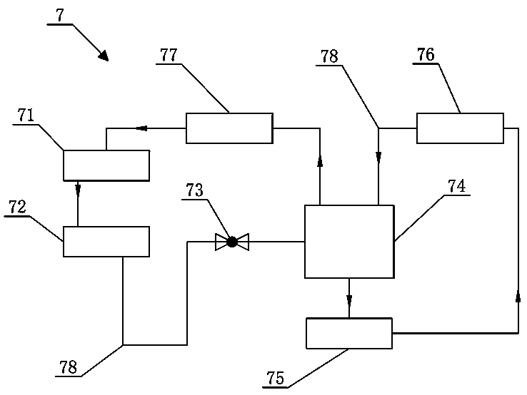
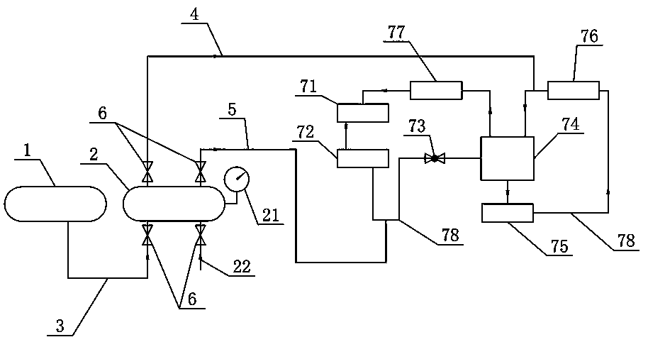
[0034] figure 2 with image 3 The refrigerant charging method of the water-cooled oil cooling refrigeration system of this embodiment is shown, and the charging method is mainly composed of the refrigerant container 1, the distribution station 2, the main pipe 3, the first distribution pipe 4 and the second distribution pipe 5. The device fills the water-cooled oil cooling refrigeration system 7 with refrigerant, the distribution station 2 is equipped with a pressure gauge 21, the refrigerant container 1 and the distribution station 2 are connected by the main pipe 3, and one end of the first distribution pipe 4 is connected to the distribution station 2. The other end is connected to the connecting pipe 78 between the low-pressure circulating accumulator 74 and the evaporator 76, one end of the second distribution pipe 5 is conne...


PUM


Abstract

The invention discloses a refrigerant charging method for a water-cooling and oil-cooling refrigeration system. A refrigerant is charged into the water-cooling and oil-cooling refrigeration system through a charging device mainly composed of a refrigerant container, a distribution station, a main pipeline, a first distribution pipeline and a second distribution pipeline. A pressure gauge is arranged on the distribution station; the refrigerant container and the distribution station are connected through the main pipeline; one end of the first distribution pipeline is connected to the distribution station, and the other end of the first distribution pipeline is connected to a connecting pipeline between a low-pressure circulating reservoir and an evaporator; one end of the second distribution pipeline is connected to the distribution station, and the other end of the second distribution pipeline is connected to a connecting pipeline between a high-pressure reservoir and a throttling valve; and switch valves are arranged at the ends, close to the distribution station, of the main pipeline, the first distribution pipeline and the second distribution pipeline correspondingly. The refrigerant charging method has the advantages that the charging device simple in structure and convenient to operate is adopted, and safety, reliability, a clear procedure and high charging efficiency areachieved.

Description

Technical field [0001] The invention relates to a technology in the field of refrigeration systems, in particular to a refrigerant charging method for a water-cooled oil cooling refrigeration system. Background technique [0002] The refrigeration system is generally divided into thermosiphon oil cooling and water cooling, such as figure 1 As shown, the water-cooled oil cooling refrigeration system 7 includes a condenser 71, a high-pressure accumulator 72, a throttle valve 73, a low-pressure circulation accumulator 74, a refrigerant pump 75, an evaporator 76 and a compressor 77, and a condenser 71, a high-pressure The accumulator 72, the throttle valve 73, the low-pressure circulation accumulator 74 and the compressor 77 are connected by a connecting pipe 78 to form a loop, and the low-pressure circulation accumulator 74, the refrigerant pump 75 and the evaporator 76 are connected by the connecting pipe 78 in sequence Form another loop. [0003] In recent years, the leakage accide...

Claims


Application Information

Patent Timeline
Patent Type & Authority Patents(China)
IPC IPC(8): F25B45/00
CPCF25B45/00F25B2345/001
Inventor 陈笠曾凡杜涂怀健于永军
Owner SINOHYDRO BUREAU 8 CO LTD
Why Eureka
Try Eureka