A marine magnetometer for underwater archeology

A magnetometer and ocean technology, applied in the field of marine magnetometer for underwater archaeology, can solve the problems of difficult salvage sampling process, single hull hanging storage structure, low efficiency, etc. Eliminate the effect of high pressure damage

Active Publication Date: 2020-02-07
宿州市徽腾知识产权咨询有限公司
View PDF7 Cites 0 Cited by
  • Summary
  • Abstract
  • Description
  • Claims
  • Application Information

AI Technical Summary

Problems solved by technology

[0002] Marine magnetometers have been widely used in the development of marine engineering such as ports, waterways, anchorages, etc. for mud obstacles, pipeline detection, submarine cable routing investigation, and magnetic field measurement in important engineering waters. For underwater archaeological operations, marine magnetometers use Its characteristics can also realize the exploration and positioning of underwater relics, but the current common marine magnetometer is only a single hull swivel storage structure in structure, and there are still many deficiencies in use: 1. Magnetometers usually use hull suspension The sinking method is used for walking detection. This method requires the hull to travel in a large area on the water surface to search and detect, which is relatively inefficient; Whether the magnetic field changes are historic sites or other non-monumental sites, it is easy to cause accidental salvage and waste manpower and material resources; 3. Due to the high underwater pressure, non-metallic detection items are easy to be squeezed and destroyed underwater, which will cause serious damage to the salvage and sampling process. difficult, so the present invention provides a marine magnetometer for underwater archeology

Method used


Image

  • A marine magnetometer for underwater archeology
  • A marine magnetometer for underwater archeology
  • A marine magnetometer for underwater archeology

Examples


Embodiment approach

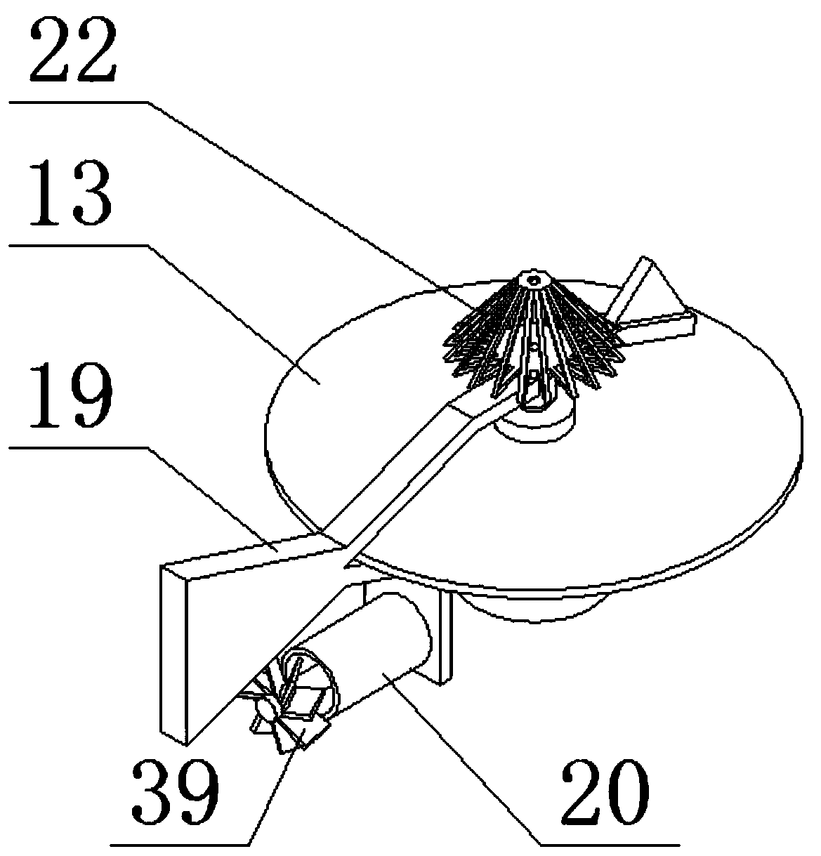
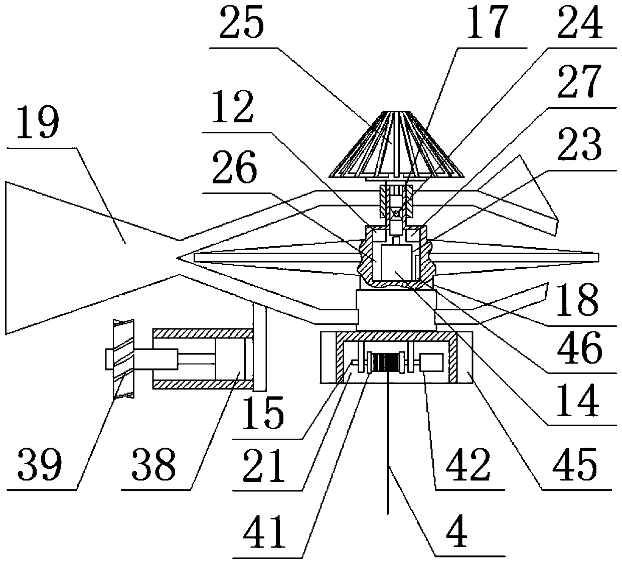
[0026] As a preferred embodiment of the present invention, the driving assembly 16 includes a driving motor 38 and a driving impeller 39 , and the driving impeller 39 is arranged at one end of the driving motor 38 .

[0027] As a preferred embodiment of the present invention, a sampling camera 40 is provided at the bottom of the sampling shaft 31 , and the sampling camera 40 is connected to a signal switch 27 through a conductive optical fiber 37 .

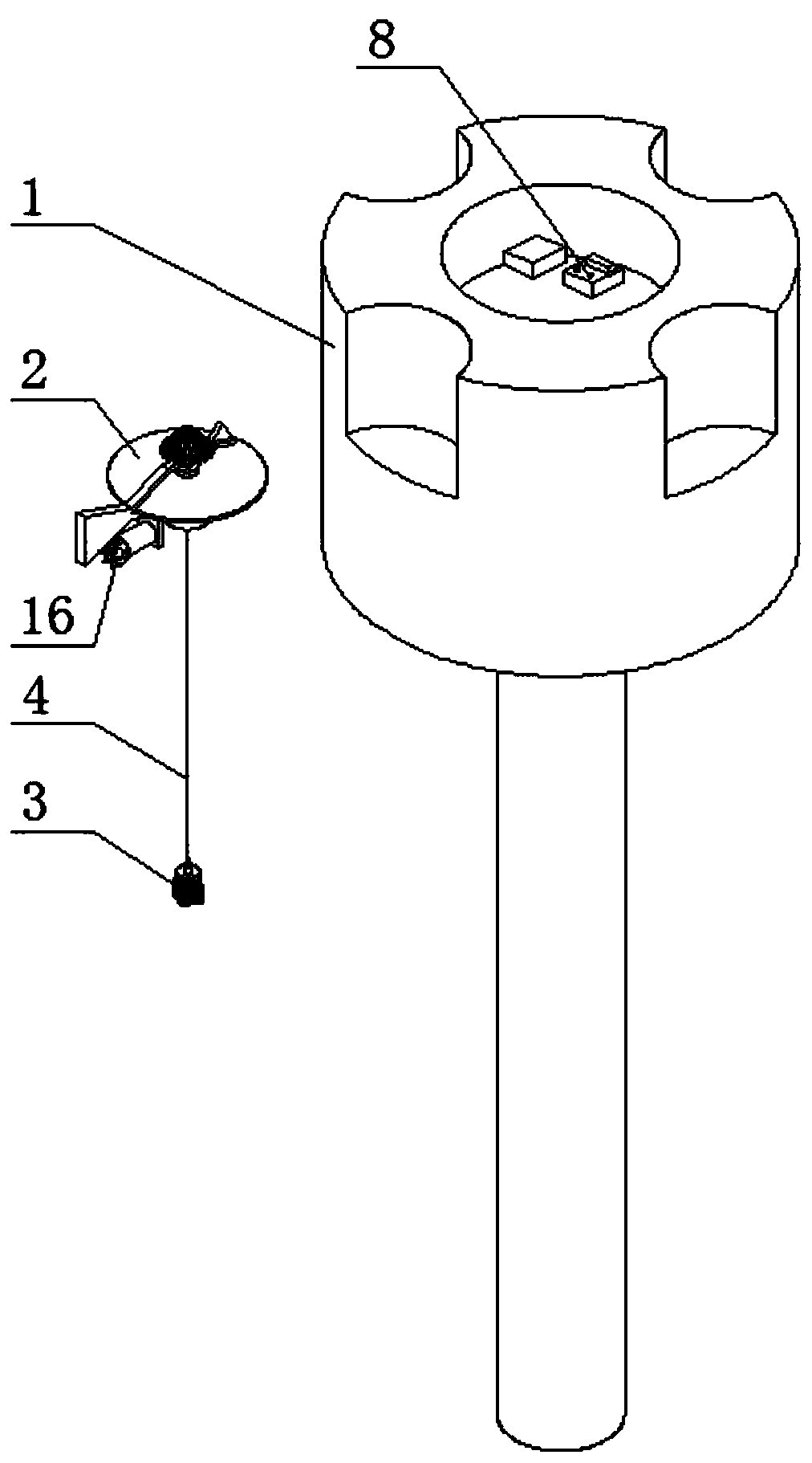
[0028] As a preferred embodiment of the present invention, the top of the sampling cage body 28 is provided with a suspension sleeve, and the power pay-off disc body 15 includes a rotating sleeve 41 and a pay-off motor 42, and the pay-off motor 42 is arranged on a rotating One end of the sleeve 41, the suspension sleeve is connected with the rotating sleeve 41 through the optical fiber lifting integrated chain 4.

[0029] As a preferred embodiment of the present invention, the wire releasing cavity 21 is sheathed with a permanent ...


PUM


Abstract

The invention discloses a marine magnetometer for underwater archaeology. The marine magnetometer comprises a gravitational magnetic cylinder body, a butterfly-shaped magnetometer disc body, a probe sampling head and an optical fiber lifting integrated chain, wherein a disc body base, a magnetic cylinder body, a storage battery and a control electric box are arranged on the gravitational magneticcylinder body, the disc body base is arranged at the top part of the magnetic cylinder body, a waterproof cavity is formed in the disc body base, the storage battery and the control electric box are arranged in the waterproof cavity, a high-power electromagnetic cylinder is arranged in the magnetic cylinder body, a coil sleeves the high-power electromagnetic cylinder, and the butterfly-shaped magnetometer disc body comprises a magnetometer, a bearing disc body, a dry ice expansion combination, a power paying-off disc body and a driving combination. The marine magnetometer extracts deep water images by means of a conductive optical fiber on the probe sampling head and facilitates visual judgment, the power paying-off disc body is arranged inside the butterfly-shaped magnetometer disc body,the power paying-off disc body can transmit the probe sampling head to a high-pressure deep water region, a sampling camera on the probe sampling head can transmit seabed images, and the seabed relicscan be identified visually.

Description

technical field [0001] The invention relates to the technical field of underwater archaeological instruments, in particular to a marine magnetometer for underwater archaeology. Background technique [0002] Marine magnetometers have been widely used in the development of marine engineering such as ports, waterways, anchorages, etc. for mud obstacles, pipeline detection, submarine cable routing investigation, and magnetic field measurement in important engineering waters. For underwater archaeological operations, marine magnetometers use Its characteristics can also realize the exploration and positioning of underwater relics, but the current common marine magnetometer is only a single hull swivel storage structure in structure, and there are still many deficiencies in use: 1. Magnetometers usually use hull suspension The sinking method is used for walking detection. This method requires the hull to travel in a large area on the water surface to search and detect, which is re...

Claims


Application Information

Patent Timeline
Patent Type & Authority Patents(China)
IPC IPC(8): G01V3/40H04N7/18
CPCG01V3/40H04N7/18Y02A90/30
Inventor 朱静轩
Owner 宿州市徽腾知识产权咨询有限公司
Why Eureka
Try Eureka