Stitching device for lens pad pasting

A technology of pressing equipment and lenses, which is applied in the direction of optical components, optics, instruments, etc., can solve the problems of increasing positioning accuracy requirements, prone to deviation, and reducing placement efficiency, so as to improve positioning accuracy, avoid continuous heating, and improve placement efficiency effect

Pending Publication Date: 2019-01-04
浙江宝乐维科技有限公司 +1
View PDF1 Cites 2 Cited by
  • Summary
  • Abstract
  • Description
  • Claims
  • Application Information

AI Technical Summary

Problems solved by technology

[0004] Although this method can achieve advantages such as having no air bubbles on the bonding surface between the master sheet and the substrate, good bonding effect without wrinkles, and excellent optical properties, the existing lens pressing equipment includes the following problems: 1. 1. Before the lower mold presses the substrate coated with adhesive and the mother sheet, the substrate coated with adhesive and the mother sheet need to be placed on the lower mold first, but because the mother sheet has a certain arc On the other hand, when placing it on the lower mold, it is necessary to make the center of the mother piece coincide with the center of the lower mold. However, manual positioning and placement requires repeated calibration by the operator, which not only reduces the placement efficiency, but also tends to be biased. Good for lens yield
[0005] 2. When using the upper and lower molds to press the substrate coated with adhesive and the master piece, it is necessary to make the spherical surfaces of the upper mold and the lower mold coincide with the centers of the two circles when they are attached, thus increasing the The positioning accuracy requirements of the existing upper and lower molds installed on the lamination equipment greatly increase the manufacturing cost and use cost of the entire lamination equipment, which is not conducive to widespread use
[0006] 3. The lens needs to be cured during the film laminating operation. The curing process can be cured by UV light, and the light of the UV light on the lens will affect the lens and the lower mold where the lens is placed and The workbench where the lower mold is placed generates heat, and because the lens film is an assembly line operation, the lower mold, the workbench and different lenses will be continuously illuminated and heated by the UV lamp, which will cause the lower mold and the workbench to continue to absorb heat during the continuous operation. heat, which is not conducive to the service life of the motor and other devices in the pressing equipment. At the same time, the lower mold and the workbench are overheated, and it is not easy for the operator to touch, which increases the difficulty of the operator's operation, and the heat dissipation of the workbench will also affect the operator's safety. The working environment has an impact, which greatly reduces the comfort of the operator's working environment

Method used


Image

  • Stitching device for lens pad pasting
  • Stitching device for lens pad pasting
  • Stitching device for lens pad pasting

Examples


Embodiment Construction

[0030]The present invention will be described in further detail below in conjunction with the accompanying drawings and embodiments. Wherein the same components are denoted by the same reference numerals. It should be noted that the words "front", "rear", "left", "right", "upper" and "lower" used in the following description refer to the directions in the drawings, and the words "bottom" and "top "Face", "inner" and "outer" refer to directions toward or away from, respectively, the geometric center of a particular component.

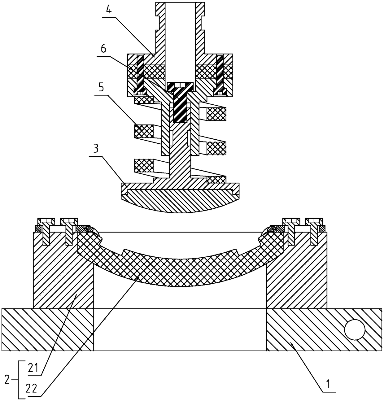
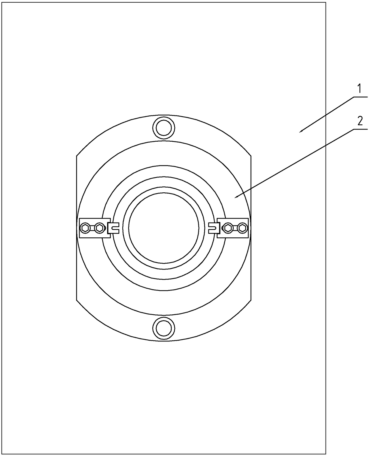
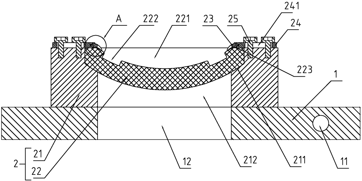
[0031] refer to Figure 1-7 As shown, a laminating device for lens filming includes a frame, a platform body 1 arranged on the frame, and a lamination head arranged on the frame above the platform body 1, wherein the lamination head is fixed on the machine The driving part on the frame is detachably connected, and the driving part is a known technology, which adopts a common design and is used to drive the pressing head close to or away from the platfo...


PUM


Abstract

The invention discloses a stitching device for lens pad pasting. The stitching device is characterized by comprising a frame, a platform body, a stitching plug and a fixture body, wherein the fixturebody is provided with an accommodation cavity and a positioning block, the positioning block includes abutting positioning edges, when an outer side wall of the lens abuts each abutting positioning edge, the center of the lens can coincide with the center of the accommodation cavity, the stitching plug includes a plug body, a mounting base body and an elastic member, the plug body is slidably connected with the mounting base body, a limit structure used for limiting separation of the plug body and the mounting base body and the sliding stroke is mounted between the mounting base body and the plug body, the platform body is provided with a heat dissipation channel, and the heat dissipation channel includes an inlet end and an outlet end. The stitching device is advantaged in that the lens can be rapidly and accurately mounted in place, positioning accuracy requirements between upper and lower dies are effectively reduced, the effect of reducing manufacturing cost and use cost of the stitching device is achieved, and the shortcoming of continuous heating due to continuous operation of a workbench in the prior art can be overcome.

Description

technical field [0001] The invention relates to the technical field of spectacle lens processing equipment, more specifically, it relates to a pressing equipment for lens film sticking. Background technique [0002] In addition to the basic configuration of the traditional spectacle lens, such as plain mirror, convex lens or concave lens, in order to add other optical effects, a layer of film that can produce a predetermined optical effect will be attached or coated on the lens, and the additional film The layer can be a polarizing film, a color filter film or a mirror protection film, etc. For example, when a polarizing film is attached to the surface of the lens, it can become a polarizing lens. [0003] At present, the Chinese patent with the notification number CN106483588B discloses a lens film processing method, which includes the following steps: Step 1: use a shaping process to process the curved surface of the substrate; Step 2: use a cleaning process to make the A...

Claims


Application Information

Patent Timeline
Patent Type & Authority Applications(China)
IPC IPC(8): G02B1/10
CPCG02B1/10
Inventor 曹汉伟
Owner 浙江宝乐维科技有限公司
Why Eureka
Try Eureka