Optical module

A technology of optical module and optical fiber, applied in the field of optical communication, can solve the problems of difficult coupling, high position accuracy requirements, long coupling time, etc.

Inactive Publication Date: 2019-01-04
HISENSE BROADBAND MULTIMEDIA TECH
View PDF3 Cites 5 Cited by
  • Summary
  • Abstract
  • Description
  • Claims
  • Application Information

AI Technical Summary

Problems solved by technology

[0005] The present application provides an optical module to overcome the problems existing in the prior art that the coup

Method used


Image

  • Optical module
  • Optical module
  • Optical module

Examples


Embodiment Construction

[0024] In order to make the purposes, technical solutions and advantages of the embodiments of the present application clearer, the technical solutions in the embodiments of the present application will be clearly and completely described below in conjunction with the drawings in the embodiments of the present application. Obviously, the described embodiments It is a part of the embodiments of this application, not all of them. Based on the embodiments in this application, all other embodiments obtained by persons of ordinary skill in the art without creative efforts fall within the protection scope of this application.

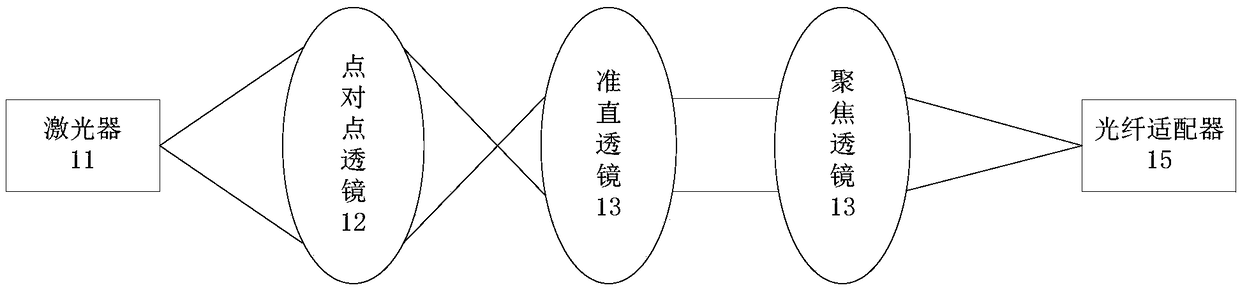
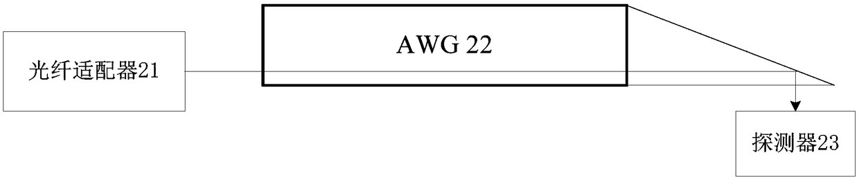
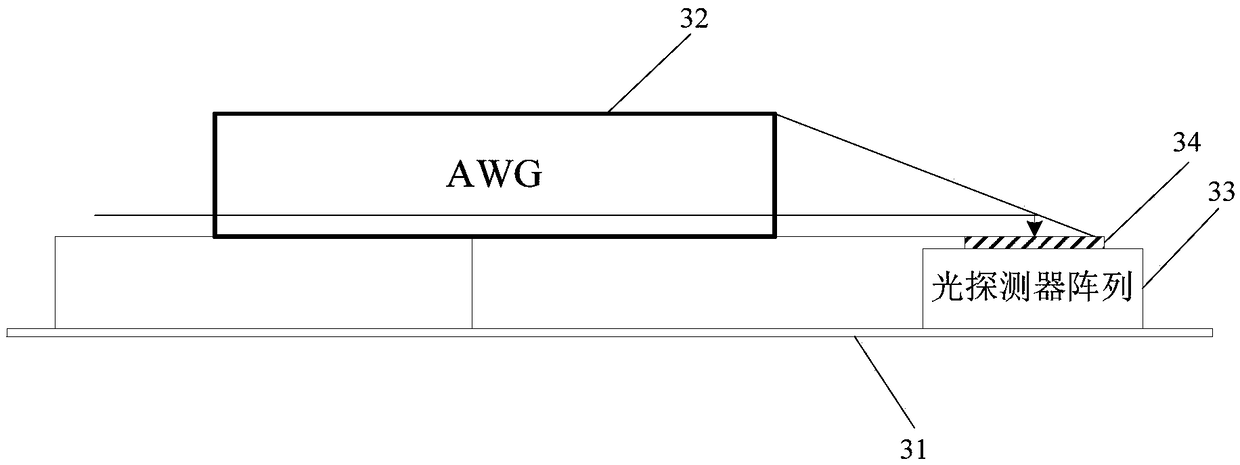
[0025] In the embodiment of the present application, the coupling process of the light and the adapter is mainly applicable to the optical module, and the optical module mainly includes a transmitter optical subassembly (TOSA) and a receiver optical subassembly (ROSA). Among them, the TOSA is mainly used to convert electrical signals into optical signals (tha...


PUM

PropertyMeasurementUnit
Viscosityaaaaaaaaaa

Abstract

The invention provides an optical module. The optical module comprises a circuit board, an arrayed waveguide grating AWG and an optical detector array which is arranged on the surface of the circuit board. Glue is coated on the surface of the optical detector array. The end of the AWG is an inclined surface. The glue is in contact with the AWG. The absolute value of the difference between the refractive index of the glue and the refractive index of the AWG is less than 10%. The light is reflected on the inclined surface of the AWG and incident to the surface of the optical detector array through the glue. According to the technical scheme, the glue is coated on the surface of the optical detector array, and the coupling efficiency can be improved and the coupling time can be shortened by using the simple optical path system, and the position accuracy requirement for each device in the optical path system can be reduced.

Description

technical field [0001] The present application relates to the technical field of optical communication, and in particular to an optical module. Background technique [0002] In the field of high-speed data communication, the integration of micro-optical assembly is getting higher and higher, and the optical system is becoming more and more complex. Especially under the premise that the size of the receiving end of the optical path is reduced and the accuracy is improved, the coupling efficiency of light and adapters becomes particularly important. . [0003] In the prior art, the way to improve the coupling efficiency of the light and the adapter is mainly to improve the coupling efficiency of the light and the adapter by reducing the light spot at the output end of the optical path by using lens combination. For example, a multi-lens coupled optical system may include a laser, a point-to-point lens, a collimator lens, a focusing lens, and a fiber adapter with an isolator, ...

Claims


Application Information

Patent Timeline
IPC IPC(8): G02B6/42
Inventor 刘维伟唐永正
Owner HISENSE BROADBAND MULTIMEDIA TECH
Why Eureka
Try Eureka