Yaw frame used for helicopter dynamic flight simulator

A dynamic flight and simulator technology, applied in the field of yaw frame, can solve problems such as unsuitable centrifugal field and unsatisfactory working conditions, and achieve the effects of enhanced welding reliability, compact structure, and enhanced bottom force

Active Publication Date: 2019-01-04
GENERAL ENG RES INST CHINA ACAD OF ENG PHYSICS
View PDF12 Cites 0 Cited by
  • Summary
  • Abstract
  • Description
  • Claims
  • Application Information

AI Technical Summary

Problems solved by technology

[0006] 1. It is used under the centrifugal field, but it mainly bears the tensile stress, and cannot meet the working conditions of large overturning moment under the centrifugal field.
[0007] 2. Functionally, it provides yaw freedom, but it works in a normal environment and is not suitable for centrifugal fields

Method used


Image

  • Yaw frame used for helicopter dynamic flight simulator
  • Yaw frame used for helicopter dynamic flight simulator
  • Yaw frame used for helicopter dynamic flight simulator

Examples


Embodiment 1

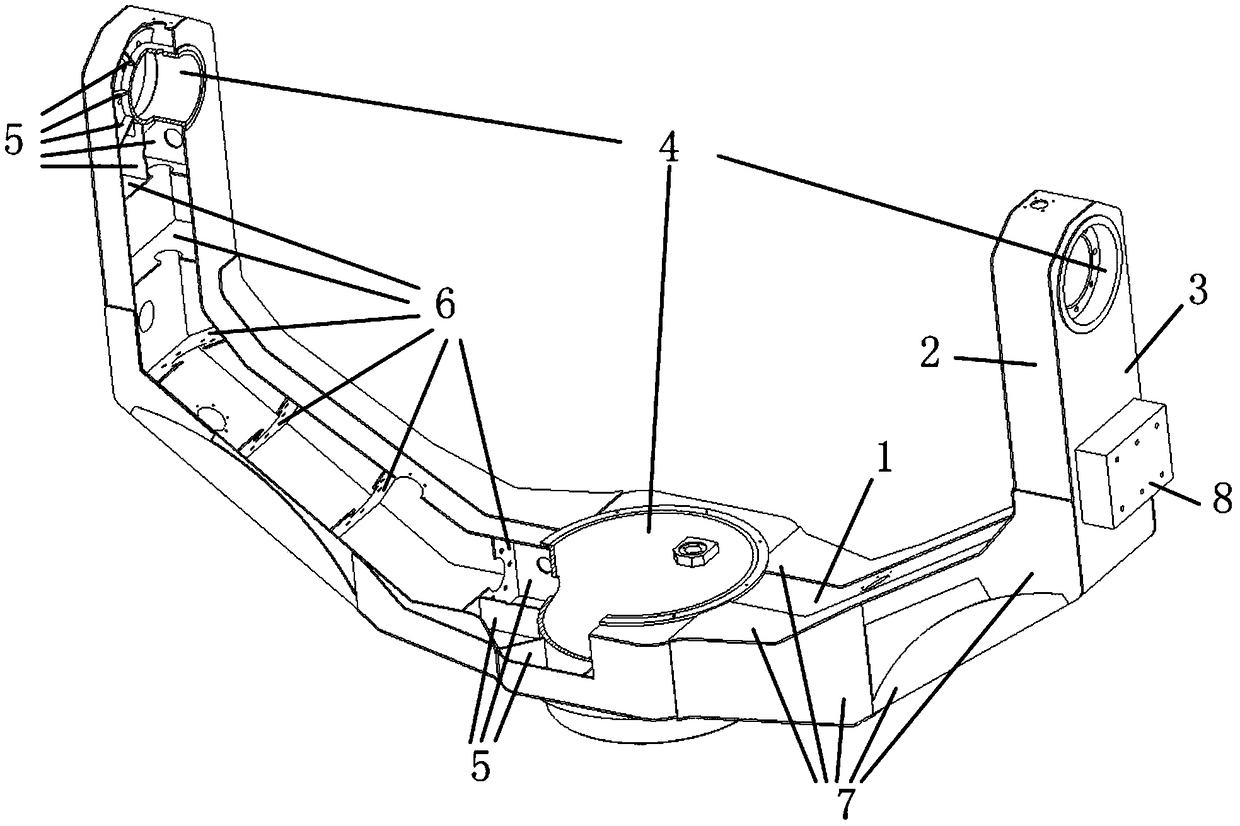
[0053] Example 1, such as figure 1 Shown:

[0054] Yaw boxes for helicopter dynamic flight simulators, including:

[0055] U-shaped inner ring plate 1;

[0056] U-shaped outer ring plate 3;

[0057] Two U-shaped side plates 2; U-shaped inner ring plate 1, U-shaped outer ring plate 3, and two U-shaped side plates 2 are connected and combined to form a closed hollow U-shaped structure, and the opening of the U-shaped structure is installed vertically upward; The bottom and upper ends of the U-shaped structure are installed with shaft hole assemblies 4, the shaft hole assemblies 4 at the bottom of the U-shaped structure are installed vertically, and the shaft hole assemblies 4 at the upper ends of the U-shaped structure are installed horizontally. The shaft hole assemblies 4 at both ends of the upper part of the U-shaped structure are concentric.

[0058]The shaft hole assembly 4 at the bottom end of the yaw frame is connected to the end of the centrifuge arm through the turn...

Embodiment 2

[0059] Example 2, such as figure 1 Shown:

[0060] The difference between this embodiment and Embodiment 1 is that the thickness of the inner ring plate 1, the outer ring plate 3 and the two side plates 2 in the hollow U-shaped structure gradually becomes thinner from the bottom to the upper two ends, and the size gradually becomes smaller.

[0061] The thickness of the yaw frame gradually becomes thinner from the bottom to the upper two ends, so that the structural strength matches the stress condition, and the distribution of materials is optimized to make the structure lightweight; the size of the yaw frame gradually decreases from the bottom to the upper ends, enhancing The ability of the yaw frame to withstand the overturning moment.

Embodiment 3

[0062] Example 3, such as figure 1 Shown:

[0063] The difference between this embodiment and Embodiment 1 is that a plurality of vertical ribs 6 are evenly arranged inside the hollow U-shaped structure, and the four sides of each vertical rib 6 are respectively fixedly connected to the inner ring plate 1, the outer ring plate 3 and two Side panels 2.

[0064] A plurality of vertical ribs strengthen the connection between the inner ring plate 1, the outer ring plate 3 and the two side plates 2 to form a closed box frame structure, which can improve the force bearing and the structural strength and rigidity.


PUM


Abstract

The invention discloses a yaw frame used for a helicopter dynamic flight simulator. The yaw frame adopts design of a box-frame welding structure, a reinforcement form of multiple vertical rib plates is adopted inside the yaw frame, and so, the strength and the rigidity of the structure are improved, and the quality is reduced at the same time; and compared with a frame type structure, the box-frame structure forms a closed bearing force, and the bearing force is more per unit mass. Compared with a cast structure, a selectable material is higher in strength, the thickness of the material is thinner, the material has no tissue defects, the cost can be reduced, a reinforced rib plate structure can be flexibly and rationally designed, and the strength and the rigidity of the structure are improved through a partially closed structure, the welding reliability is simultaneously enhanced, and requirements of strength, rigidity and light weight of the structure are satisfied. A reinforcing plate structure is externally attached to the bottom and a waist position of the yaw frame, which is beneficial to strengthen a structure of a bending position of the yaw frame and to improve the stress,and is beneficial to improve the strength and the rigidity of the structure b utilizing minimum materials. A counterweight is designed to match a center of mass of an overall yaw frame system near acenter line of a rotating shaft, in order to meet the requirements of rotation accuracy, reduction of eccentric load vibration, and the like.

Description

technical field [0001] The invention belongs to the technical field of helicopter dynamic flight simulation, and in particular relates to a yaw frame for a helicopter dynamic flight simulator. Background technique [0002] Helicopter dynamic flight simulator is a kind of simulation training equipment based on centrifuge platform. It can realize the attitude change of any three degrees of freedom of the pilot in space under continuous load, and it is easy to induce a variety of spatial orientation disorders. It can simulate a variety of abnormal flight states in the ground environment, and has achieved the ability for the pilot to recognize the orientation disorder and grasp the environment in which the orientation disorder occurs. , forms of expression and ways to overcome them. Compared with the dynamic flight simulator, it has an additional U-shaped yaw frame in terms of structure, providing yaw freedom for the cockpit. It bears the combined bending and torsional load do...

Claims


Application Information

Patent Timeline
Patent Type & Authority Applications(China)
IPC IPC(8): G05D1/10G05D1/08
CPCG05D1/0808G05D1/101Y02T90/00
Inventor 何阳蒋春梅宋琼黎启胜陈磊赵世鹏胡荣华白俊林尹鹏
Owner GENERAL ENG RES INST CHINA ACAD OF ENG PHYSICS
Why Eureka
Try Eureka