
A light field image rotation error correction method

A technology of rotation error and correction method, which is applied in the field of image processing, can solve problems such as low accuracy of rotation angle solution, unsatisfactory correction effect, and large calculation amount, so as to reduce calculation time, reduce data calculation amount, and solve calculation amount big effect

Active Publication Date: 2019-01-04
HARBIN INST OF TECH
View PDF3 Cites 18 Cited by
  • Summary
  • Abstract
  • Description
  • Claims
  • Application Information

AI Technical Summary

Problems solved by technology

[0005] The purpose of the present invention is to solve the problems of large amount of calculation, long time consumption, low accuracy of solving the rotation angle and unsatisfactory correction effect existing in the existing light field image rotation error correction method, thereby providing a light field image rotation error correction method

Method used


Image

  • A light field image rotation error correction method
  • A light field image rotation error correction method
  • A light field image rotation error correction method

Examples


Embodiment Construction

[0053] The following will clearly and completely describe the technical solutions in the embodiments of the present invention with reference to the accompanying drawings in the embodiments of the present invention. Obviously, the described embodiments are only some, not all, embodiments of the present invention. Based on the embodiments of the present invention, all other embodiments obtained by persons of ordinary skill in the art without creative efforts fall within the protection scope of the present invention.

[0054] It should be noted that, in the case of no conflict, the embodiments of the present invention and the features in the embodiments can be combined with each other.

[0055] The present invention will be further described below in conjunction with the accompanying drawings and specific embodiments, but not as a limitation of the present invention.

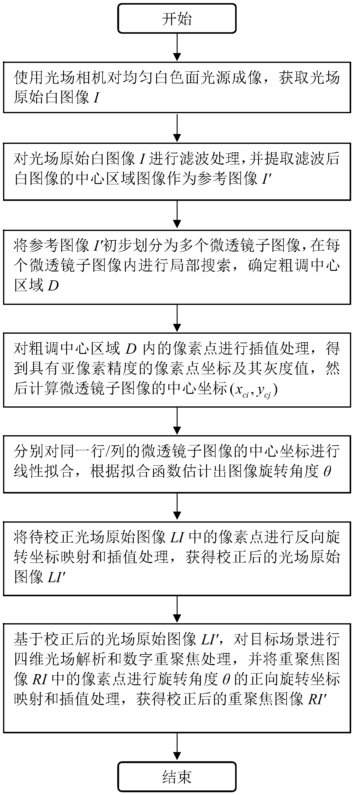
[0056] figure 1 It is a basic flowchart of a light field image rotation correction method provided in this embo...


PUM


Abstract

A light field image rotation error correction method relates to the field of image processing, in order to solve the problems of large calculation amount, long time consuming, low precision of rotation angle solution and undesirable correction effect existing in the prior light field image rotation error correction method. The method comprises steps: acquiring the original white image of the lightfield; extracting a reference image; the reference image being initially divided into a plurality of micro-transmissive mirror images, and the coarse adjustment center region being determined; calculating a center coordinate of each micro-transparent mirror image; the image rotation angle being estimated by fitting the center coordinates linearly; the pixel points in the original image of the light field to be corrected being subjected to reverse rotation coordinate mapping and interpolation processing to obtain the corrected original image of the light field; the four-dimensional light fieldanalysis and digital refocusing being carried out on the target scene to obtain the refocused image; the pixel points in the refocused image being mapped and interpolated to obtain the corrected refocused image. The invention is suitable for correcting light field images.

Description

technical field [0001] The invention relates to the field of image processing, in particular to a light field image rotation error correction technology. Background technique [0002] The light field camera applies light field imaging technology, which can acquire and display the multi-angle light field radiation intensity distribution from space objects through a single exposure. Unlike traditional imaging devices that only record spatial information, it can simultaneously record two-dimensional spatial information and two-dimensional angular information of a four-dimensional light field. The preservation of light radiation angle information provides the required light field data for multi-view imaging, digital refocusing and 3D reconstruction of the target scene. In recent years, a variety of reconstruction algorithms for complex scenes have been developed using light field image data, and light field cameras are gradually being used in engineering fields such as high tem...

Claims


Application Information

Patent Timeline
IPC IPC(8): G06T3/60
CPCG06T3/608
Inventor 李苏宁袁远刘彬董士奎谈和平
Owner HARBIN INST OF TECH
Learn More