Supercharge Your Innovation With Domain-Expert AI Agents!

A method and apparatus for charge and discharge control

A charge-discharge control and charge-discharge device technology, applied in the field of solar energy, can solve the problems of low utilization rate of solar battery power and the like

Inactive Publication Date: 2019-01-04
HANERGY MOBILE ENERGY HLDG GRP CO LTD
View PDF3 Cites 0 Cited by
  • Summary
  • Abstract
  • Description
  • Claims
  • Application Information

AI Technical Summary

Problems solved by technology

[0003] Embodiments of the present invention provide a charge and discharge control method and device to solve the problem of relatively low power utilization of solar cells in existing vehicle power supply systems

Method used


Image

  • A method and apparatus for charge and discharge control
  • A method and apparatus for charge and discharge control
  • A method and apparatus for charge and discharge control

Examples


Embodiment Construction

[0060] The following will clearly and completely describe the technical solutions in the embodiments of the present invention with reference to the accompanying drawings in the embodiments of the present invention. Obviously, the described embodiments are some of the embodiments of the present invention, but not all of them. Based on the embodiments of the present invention, all other embodiments obtained by persons of ordinary skill in the art without creative efforts fall within the protection scope of the present invention.

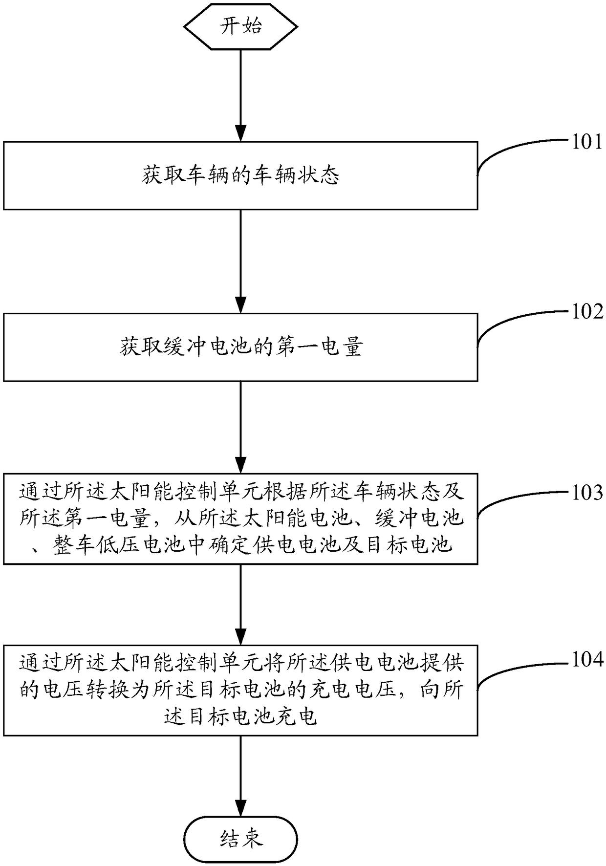
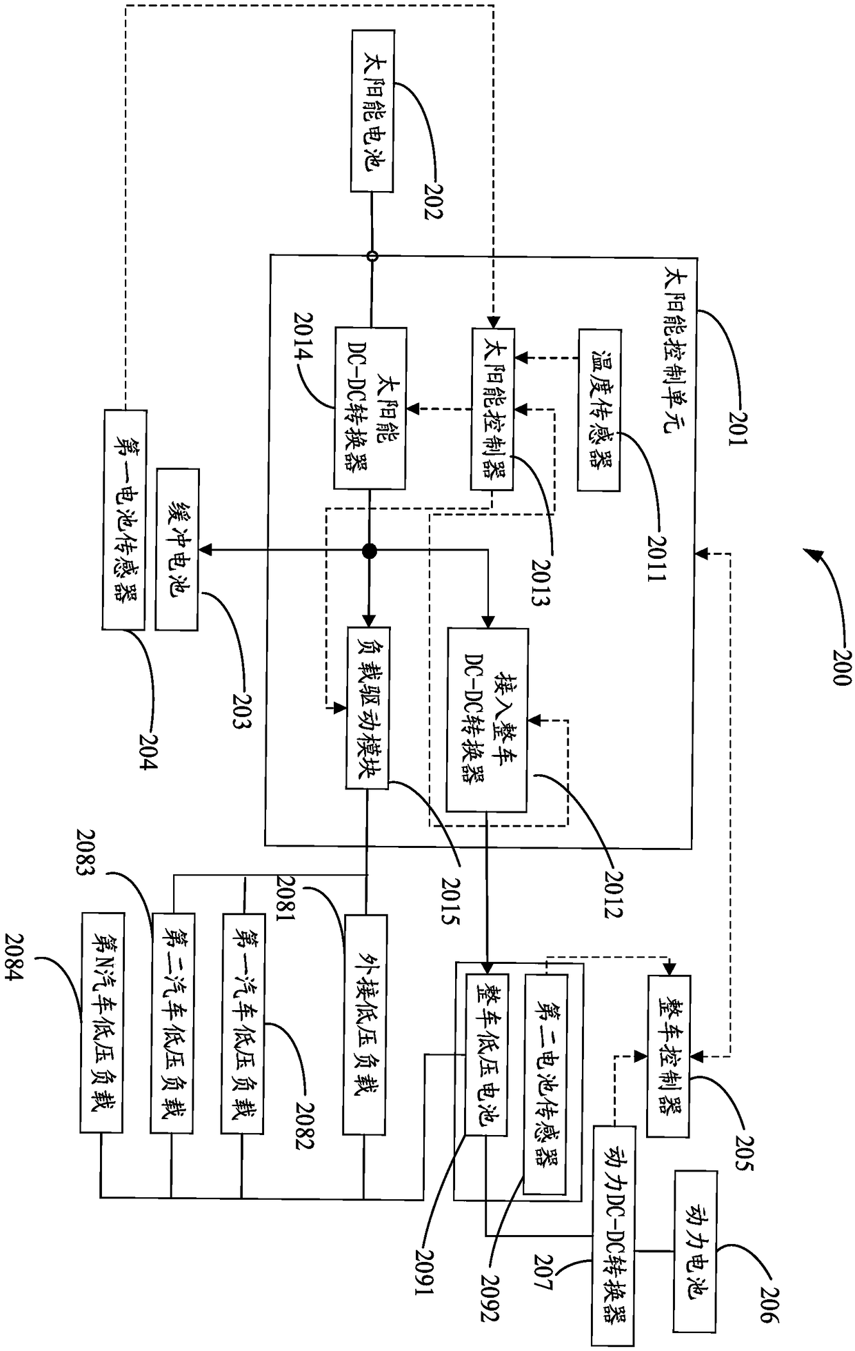
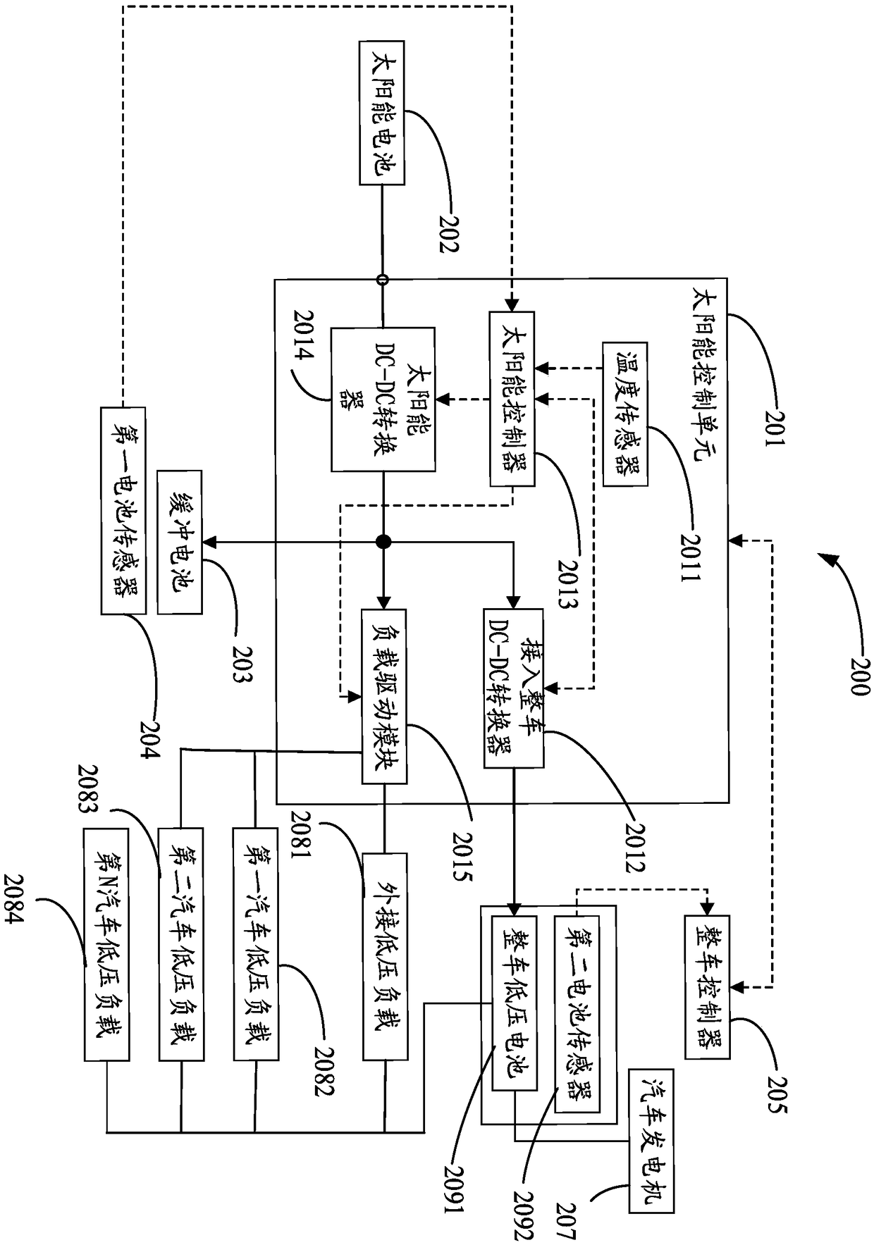
[0061] see figure 1 , figure 1 It is one of the flowcharts of the charging and discharging control method provided by the embodiment of the present invention. The charge and discharge control method is used in a charge and discharge control device connected to a vehicle, and the charge and discharge control device includes a solar battery, a buffer battery, a vehicle low-voltage battery and a solar control unit. For example, see Figure 2-3 , figu...


PUM


Abstract

The invention relates to the technical field of solar energy, and provides a charging and discharging control method and a device. The charging and discharging control method comprises the following steps: acquiring a vehicle state of the vehicle; Acquiring a first amount of power of the buffer battery; Determining a power supply battery and a target battery from a solar battery, a buffer batteryand a whole vehicle low-voltage battery by a solar energy control unit according to a vehicle state and a first electric quantity; The voltage supplied from the power supply battery is converted intoa charging voltage of the target battery by the solar control unit, and the target battery is charged. As that power supply battery and the target battery can be flexibly determined from the solar cell, the cushion battery and the whole vehicle low-voltage battery, the power supply battery can be controlled to supply power to the target battery, the power quantity of the solar cell can be fully utilized, and the power utilization rate of the solar cell can be improved.

Description

technical field [0001] The invention relates to the technical field of solar energy, in particular to a charging and discharging control method and device. Background technique [0002] The existing vehicle power supply system has single power supply mode and dual power supply mode. The mode in which the supplementary power source is a generator or a power battery is called a single power supply mode. power mode. In the existing dual power supply mode, the utilization rate of the solar battery power is relatively low due to reasons such as the limited use range of the solar battery power supply on the vehicle. It can be seen that the existing vehicle power supply system has the problem of relatively low power utilization rate of solar cells. Contents of the invention [0003] Embodiments of the present invention provide a charge and discharge control method and device to solve the problem of relatively low power utilization rate of solar cells in the existing vehicle pow...

Claims


Application Information

Patent Timeline
Patent Type & Authority Applications(China)
IPC IPC(8): H02J7/35
CPCH02J7/35Y02E10/56
Inventor 杨秋胜
Owner HANERGY MOBILE ENERGY HLDG GRP CO LTD
Features
  • R&D
  • Intellectual Property
  • Life Sciences
  • Materials
  • Tech Scout
  • Unparalleled Data Quality
  • Higher Quality Content
  • 60% Fewer Hallucinations
Learn More