Tool spindles of devices for the finishing of optically active surfaces on workpieces

An optically effective surface, tool spindle technology, used in metal processing equipment, optical surface grinders, grinding/polishing equipment, etc., can solve the problem that the axial mobility of the tool mounting head is not so fine and sensitive, and achieve easy movement and smoothness. The effect of improved running smoothness, reduced machining time and high polishing quality

Active Publication Date: 2020-12-25
SATISLOH AG
View PDF13 Cites 0 Cited by
  • Summary
  • Abstract
  • Description
  • Claims
  • Application Information

AI Technical Summary

Problems solved by technology

[0012] Although such slotted shaft guides are readily available on the market, for example, from Nippon Bearing Co., Ltd. in Ojiya, Japan, as stated in the introduction to document WO 2012 / 123120A1, its The disadvantage is that the axial mobility of the tool mounting head is not as fine and sensitive compared to the prior art, where the torque transmission from the polishing tool to the spindle shaft is arranged on the axis of the diaphragm chuck tool To the rear of the guide (guide element 176)

Method used


Image

  • Tool spindles of devices for the finishing of optically active surfaces on workpieces
  • Tool spindles of devices for the finishing of optically active surfaces on workpieces
  • Tool spindles of devices for the finishing of optically active surfaces on workpieces

Examples


Embodiment Construction

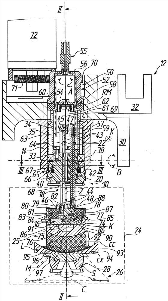
[0041] As a possible application or place of use of the tool spindle 10 according to the invention, in figure 1 In general, 12 denotes a device for finishing the optically effective surfaces cc, cx of a workpiece such as a spectacle lens L. As shown in FIG. exist figure 1 The device 12 , only partially illustrated in , constitutes a subassembly of the polishing machine described in more detail in the earlier international application PCT / EP2015 / 001857 (WO2016 / 058663A1 ). The apparatus 12 and polisher will be described below only to the extent necessary to understand the invention. In addition, here, in order to avoid repetition, regarding the structure and function of the device 12 and the polishing machine, reference can be made explicitly to the earlier international application PCT / EP2015 / 001857 (WO2016 / 058663A1).

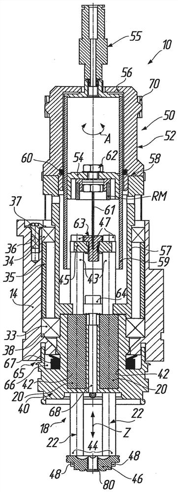
[0042]The tool spindle 10 comprises a spindle housing 14 and a tool holding section 16 which protrudes beyond the spindle housing 14 and is axially adjustab...


PUM


Abstract

The invention relates to a tool spindle (10) of a device (12) for finishing an optically active surface (cc, cx) on a workpiece (L), with a spindle housing (14) and a tool holding section protruding beyond the housing (16). The tool holding section is axially advanced (advance axis Z) towards the workpiece along the tool axis of rotation via a guide assembly (18) which is housed in the spindle housing Can be rotated about the tool rotation axis (A). For axial advancement of the tool holding section, the guide assembly has: a plurality of linear mounting elements (20) evenly distributed around the tool axis of rotation; and corresponding pairs of guide rods (22), which are connected in a tension- and pressure-resistant manner to the tool holding section. As a result, the tool holding section can follow the macroscopic geometry of the workpiece in a smooth and fine manner when machining the microscopic geometry of the workpiece.

Description

technical field [0001] The invention generally relates to a tool spindle of an installation for finishing an optically active surface of a workpiece. In particular, the invention relates to a tool spindle of a device such as is widely used for the finishing of optically active surfaces of spectacle lenses in so-called "prescription (RX) workshops", i.e. for the production of individual spectacle lenses according to prescriptions. Production facilities. However, this should not be interpreted as limiting in any way; on the contrary, it can also be considered for precision optics (lens production, mirror production and casting mold production), it can be seen that in precision optics, there is an orientation towards In particular there is a growing trend towards more complex parts with aspheric surfaces and freeform surfaces. [0002] When reference is made below to workpieces with optically active surfaces by the example of "spectacle lenses", it is to be understood that this...

Claims


Application Information

Patent Timeline
Patent Type & Authority Patents(China)
IPC IPC(8): B24B13/00B24B41/053B23Q1/70B23Q5/32
CPCB24B13/00B24B41/053
Inventor S·沃伦道夫H·谢弗M·莱茨
Owner SATISLOH AG
Why Eureka
Try Eureka