
Zigzag cooling mechanism

A cooling mechanism and blanking technology, which is used in the cleaning/processing machinery of casting materials, casting molding equipment, metal processing equipment, etc., can solve problems such as increasing costs, save energy, prolong falling time, and reduce consumption Effect

Inactive Publication Date: 2019-01-08
YUZHOU KUNLUN MOLD CO LTD
View PDF0 Cites 0 Cited by
  • Summary
  • Abstract
  • Description
  • Claims
  • Application Information

AI Technical Summary

Problems solved by technology

The cooling step generally uses a vibrating screen for cooling. This cooling method uses an electric loading device. This type of device is always in an electric state, which virtually increases the cost.

Method used


Image

  • Zigzag cooling mechanism

Examples


Embodiment

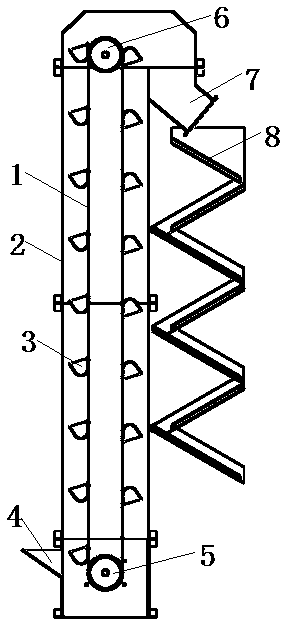
[0013] A zigzag cooling mechanism, comprising a lifting device and a feeding slideway, the lower end of the lifting device is provided with a material inlet, the upper end of the lifting device is provided with a discharge port 4, and the lifting device includes a lifting belt 1, a casing 2, a hopper 3, a feeding Port 4, driving pulley 5, driven pulley 6, discharge port 7, blanking slide 8, and blanking channel 9, the lifting device lifts the coated sand to be cooled to a certain height, and the The casing 2 is a casing placed vertically, the bottom of the casing 2 is provided with a driven pulley 5, the top of the casing is provided with a driving pulley 4, the driving pulley 4 is connected to the power unit, and the driving pulley 4 is connected with the driven pulley 5 through the lifting belt 1, the lifting belt 1 is provided with a plurality of hoppers 2, the discharge port 7 of the lifting device corresponds to the discharge channel 9, and the discharge channel 9 It incl...


PUM


Abstract

The invention provides a zigzag cooling mechanism. The zigzag cooling mechanism comprises a lifting device and a discharging slideway, wherein a feeding opening is formed in the lower end of the lifting device; a discharging opening is formed in the upper end of the lifting device; the lifting device lifts to-be-cooled precoated sand to certain height; the discharging opening of the lifting devicecorresponds to the discharging slideway; a discharging channel comprises a material receiving hopper and a plurality of discharging skid hoppers; an upper end opening of the material receiving hoppercorresponds to a discharging opening in a housing; the plurality of discharging skid hoppers are connected end to end and are vertically arranged into a zigzag structure; a lower end opening of the material receiving hopper corresponds to the uppermost discharging skid hopper; during use, the falling stroke of the precoated sand is increased by a discharging channel with a zigzag structure, so that contacted area between the precoated sand and air is enlarged, falling time of the precoated sand is prolonged, and the precoated sand is enabled to be in full contact with the air and sufficientlycooled.

Description

technical field [0001] The invention belongs to the technical field of equipment for producing coated sand, and in particular relates to a zigzag cooling mechanism. Background technique [0002] The coated sand casting process is a mixed method of coated sand, which has gone through four stages: dry mixing method, cold coating method, warm coating method, and hot coating method. The production of coated sand is almost always using the hot coating method. , The thermal coating process is to heat the raw sand to a certain temperature, then mix it with resin, urethane solution and calcium stearate, and then cool, crush and sieve it. The cooling step generally uses a vibrating screen for cooling. This cooling method uses an electric loading device. This type of device is always in an electric state, which virtually increases the cost. Contents of the invention [0003] Aiming at the technical problems existing in the cooling of the existing coated sand, the present invention ...

Claims


Application Information

Patent Timeline
Patent Type & Authority Applications(China)
IPC IPC(8): B22C5/08
CPCB22C5/08
Inventor 李向阳
Owner YUZHOU KUNLUN MOLD CO LTD
Learn More