Cooling and vibration reduction tool bar applied to machining for large-pitch screw rod

A technology with a large pitch and a shank, which is applied to tools for lathes, metal processing equipment, tool holders, etc., and can solve the problems of poor cooling effect in multi-blade cutting, poor cooling effect in multi-blade cutting, and large instantaneous vibration amplitude. , to achieve the effect of compact structure, reduced stiffness and efficient cooling

Pending Publication Date: 2019-01-08
HARBIN UNIV OF SCI & TECH
View PDF0 Cites 4 Cited by
  • Summary
  • Abstract
  • Description
  • Claims
  • Application Information

AI Technical Summary

Problems solved by technology

[0004] The present invention aims at the existing large-pitch screw cutter bar that cannot be applied to the vibration frequency bandwidth, solves the defects of large instantaneous vibration amplitude, poor multi-blade cutting cooling effect, and poor cutter bar rigidity, and provides a vibration frequency bandwidth that can be applied and solves the problem of Cooling and damping tool holders with problems such as large instantaneous vibration amplitude, poor cooling effect in multi-edged cutting, and poor rigidity of the tool holder

Method used


Image

  • Cooling and vibration reduction tool bar applied to machining for large-pitch screw rod
  • Cooling and vibration reduction tool bar applied to machining for large-pitch screw rod
  • Cooling and vibration reduction tool bar applied to machining for large-pitch screw rod

Examples


Embodiment 1

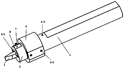
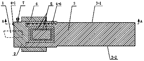
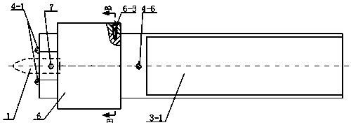
[0025] Embodiment 1, combining figure 1 , figure 2 , image 3 , Figure 4 , Figure 5 , Figure 6 and Figure 7This embodiment is described. In this embodiment, the present invention relates to a cooling and damping cutter bar applied to large-pitch screw processing, and a cooling and vibration-damping cutter rod applied to large-pitch screw processing. It is characterized in that, It comprises a turning tool 1, a tool holder head 2, a cutter holder body 3, a cooling unit 4, a damping unit 5 and a protective ring 6, the turning tool 1 is fixed on one end of the cutter holder head 2, and the other end of the cutter holder head 2 One end is provided with a protrusion, and one end of the cutter body 3 is provided with a groove. The damping unit 5 is located in the groove of the cutter body 3 and is a transition fit. The protrusion of the cutter head 2 and the cutter body 3 matched with the groove, used to fix the damping unit 5, the protective ring 6 is fastened on the out...


PUM


Abstract

The invention discloses a cooling and vibration reduction tool bar applied to machining for a large-pitch screw rod, and belongs to the technical field of machining. Aiming at the existing problems, the invention provides a cooling and vibration reduction tool bar applicable to a wide vibration frequency band, and solving the problems of high instantaneous vibration amplitude, poor cooling effectof multi-edge cutting, and the like. The invention discloses a cooling and vibration reduction tool bar applied to machining for a large-pitch screw rod. The cooling and vibration reduction tool bar applied to machining for the large-pitch screw rod comprises a cooling unit, a tool bar body, a tool bar head, a turning tool, a vibration reduction unit and a protection ring, wherein the vibration reduction unit is located at a groove of the tool bar body; a bulge part of the tool bar head is matched with the groove of the tool bar body, and fixes the vibration reduction unit; the turning tool isfixed to one end away from the bulge part, of the tool bar head; the cooling unit comprises a cooling spray head, a cooling liquid branch flow channel, a cooling liquid turning joint, a cooling liquid flow-distribution joint, a cooling liquid main flow channel and a cooling liquid connection hole; the cooling liquid branch flow channel is formed in the tool bar head and communicates with the cooling spray head; and the cooling spray head is arranged on one end surface for fixing the turning tool, of the tool bar head. The cooling and vibration reduction tool bar applied to machining for the large-pitch screw rod is mainly applied to machining for the large-pitch screw rod.

Description

technical field [0001] The invention relates to a cooling and vibration-damping cutter bar used in the processing of large-pitch screw rods, and belongs to the technical field of mechanical processing. Background technique [0002] Large-pitch screw parts are common important parts in large-scale equipment, such as large-scale press adjustment screws, main shaft ends and fastening screws of large-scale ship propellers, extrusion screws in plastic and rubber industry equipment, and wind power equipment. Bolts and more. In the application of large-pitch screw parts, often due to the problem of its manufacturing accuracy, problems such as thread disorder during the working process, poor motion accuracy and positioning accuracy are often caused, and the main cause of these problems is tool vibration during screw processing . In the processing of large-pitch screw, due to its characteristics of high feed, large depth of cut, and large load, it causes obvious vibration during th...

Claims


Application Information

Patent Timeline
Patent Type & Authority Applications(China)
IPC IPC(8): B23B27/06B23B27/10B23B29/12
CPCB23B29/12B23B27/065B23B27/10
Inventor 李哲李景帅周亚栋崔玉龙王少宇
Owner HARBIN UNIV OF SCI & TECH
Why Eureka
Try Eureka