
Discharging equipment for rapid cutting equipment for steel door metal steel

A rapid cutting and equipment technology, which is applied in the direction of metal processing equipment, shearing devices, manufacturing tools, etc., can solve the problems of low adjustment accuracy, low cutting accuracy, and low cutting accuracy, so as to improve cutting accuracy and facilitate operation , Improve the effect of cutting efficiency

Inactive Publication Date: 2019-01-08
湖州欧贝得门业有限公司
View PDF0 Cites 0 Cited by
  • Summary
  • Abstract
  • Description
  • Claims
  • Application Information

AI Technical Summary

Problems solved by technology

The metal frame is welded by metal steel, and the metal steel needs to be cut with a cutting machine according to the actual use when it is used; however, the existing cutting machine needs to manually place the metal steel in place when cutting. Then adjust the appropriate cutting length. After the cutting is completed, it is necessary to manually pick up the material, which is not only troublesome to operate, but also low in efficiency.
At the same time, manually adjusting the cutting length is not only complicated to operate, but also the adjustment accuracy is not high, resulting in lower cutting accuracy
Therefore, the existing technology has the problems of low efficiency and low cutting accuracy.

Method used


Image

  • Discharging equipment for rapid cutting equipment for steel door metal steel
  • Discharging equipment for rapid cutting equipment for steel door metal steel
  • Discharging equipment for rapid cutting equipment for steel door metal steel

Examples


Embodiment Construction

[0013] The present invention will be further described below in conjunction with the accompanying drawings and embodiments, but not as a basis for limiting the present invention.

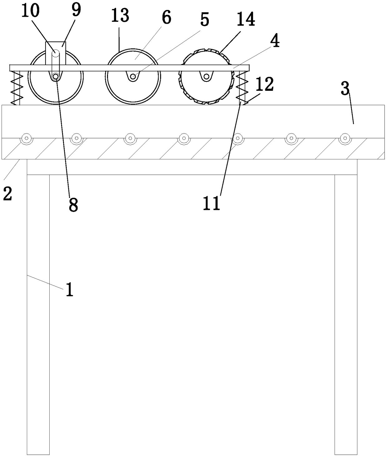
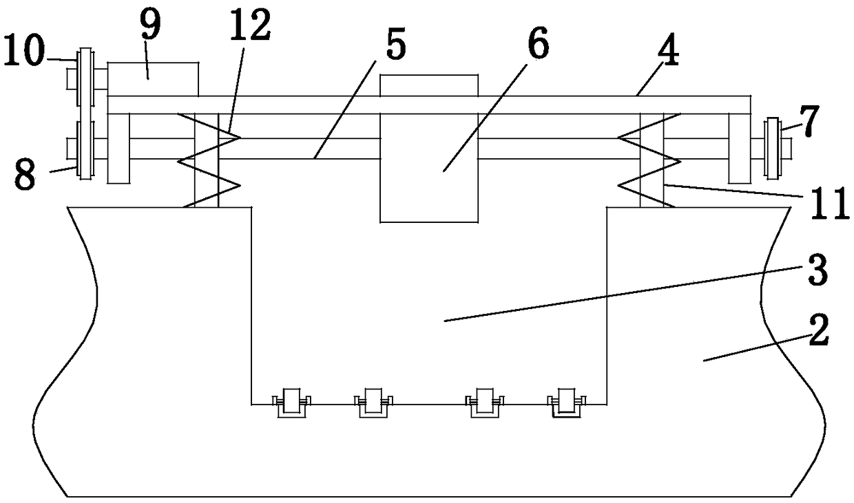
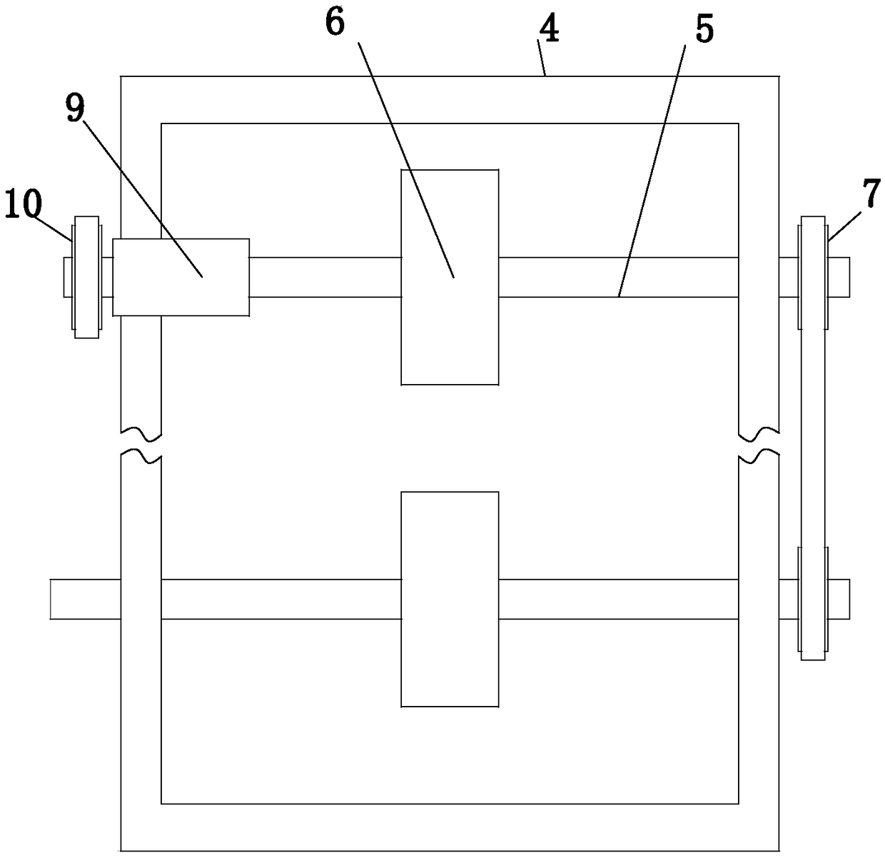
[0014] Example. The discharge equipment of metal steel rapid cutting equipment for steel doors is constituted as Figure 1 to Figure 4 As shown, it includes a frame 1, a cutting platform 2 is provided above the frame 1, a chute 3 is provided on the cutting platform 2, a support 4 is provided above the chute 3, and a set of horizontally arranged rotating shafts is provided at the lower part of the support 4 5. The middle part of the rotating shaft 5 is equipped with a pressing wheel 6 corresponding to the position of the chute 3, and one end of the rotating shaft 5 is provided with a transmission gear 7, and the adjacent transmission gears 7 are connected by a chain, and one of the rotating shafts 5 is the other One end is provided with driven gear 8, is also provided with driving motor 9 above the ...


PUM


Abstract

The invention discloses discharging equipment for rapid cutting equipment for steel door metal steel. The discharging equipment comprises a rack. A cutting platform is arranged above the rack. A sliding groove is formed in the cutting platform. A support is arranged above the sliding groove. A set of transversely-arranged rotation shafts are arranged at the lower portion of the support. Pressing wheels corresponding to the sliding groove in position are arranged at the middle portions of the rotation shafts. A transmission gear is arranged at one end of each rotation shaft. The adjacent transmission gears are connected through a chain. A driven gear is arranged at the other end of one rotation shaft. A drive motor is further arranged above the support. A drive gear is arranged at the output end of the drive motor. The drive gear and the driven gear are connected through a transmission chain. Telescopic rods are arranged between the support and the cutting platform. The telescopic rodsare sleeved with adjusting springs located between the support and the cutting platform. The discharging equipment has the characteristics that the cutting efficiency can be effectively improved, andthe cutting precision is improved.

Description

technical field [0001] The invention relates to a cutting device for steel door production, in particular to a discharge device of a metal steel rapid cutting device for steel doors. Background technique [0002] Steel doors are assembled from metal frames and metal panels. The metal frame is welded by metal steel, and the metal steel needs to be cut with a cutting machine according to the actual use when it is used; however, the existing cutting machine needs to manually place the metal steel in place when cutting. Then after adjusting the appropriate cutting length, after the cutting is completed, it is necessary to manually take out the material, which is not only cumbersome to operate, but also inefficient. At the same time, manually adjusting the cutting length is not only complicated to operate, but also the adjustment accuracy is not high, resulting in lower cutting accuracy. Therefore, the existing technology has the problems of low efficiency and low cutting preci...

Claims


Application Information

Patent Timeline
IPC IPC(8): B23D33/02
CPCB23D33/02
Inventor 钱利中
Owner 湖州欧贝得门业有限公司
Learn More