
Pressure relief valve automatic assembly equipment

A technology for assembling equipment and pressure relief valves, which is applied in the direction of assembly machines, metal processing equipment, manufacturing tools, etc., can solve the problem of being unable to meet the development trend of high efficiency, high quality and low cost, difficult to choose between processing output and processing cost, and no automation of operation mode Equipment and other issues, to achieve the effects of labor saving, high degree of automation, and high degree of functional integration

Active Publication Date: 2020-03-06
UPTON AUTOMATION SYST KUNSHAN CO LTD
View PDF19 Cites 0 Cited by
  • Summary
  • Abstract
  • Description
  • Claims
  • Application Information

AI Technical Summary

Problems solved by technology

[0003] However, due to technical constraints, the current assembly of pressure relief valves is done manually. A production line of pressure relief valves requires at least 11 workers. The processing output depends on the proficiency of the employees, and they can only be operated by old employees. The speed of new employees is only 1 / 3 of the speed of old employees. Coupled with the turnover rate of employees and other reasons, skilled employees need to be supported for a long time, and they may not be able to retain them. Moreover, the salaries of old employees are relatively high. It is difficult to choose between processing output and processing cost
Furthermore, manual operation is laborious, high cost and low production capacity
[0004] This manual assembly operation method cannot meet the development trend of high efficiency, high quality and low cost required for mass production
At present, there is no other better operation mode or automatic equipment that can solve the above problems

Method used


Image

  • Pressure relief valve automatic assembly equipment
  • Pressure relief valve automatic assembly equipment
  • Pressure relief valve automatic assembly equipment

Examples


Embodiment

[0084] Embodiment: a kind of pressure relief valve automatic assembly equipment, such as Figures 2.1 to 2.4 As shown, it includes a frame 1 and a pressure relief valve main assembly line 2 and a moving valve core assembly assembly line 3 located on the frame;

[0085] The main assembly line 2 of the pressure relief valve includes a main turntable 21, and a plurality of valve body carriers 211 are arranged on the main turntable. Device 22, round washer assembly device 23, fixed ring assembly device 24, side cap assembly assembly device 25 and spring assembly device 26;

[0086] Such as Figures 2.1 to 2.4 as shown and as Figure 7As shown, the moving spool assembly line 3 includes an auxiliary turntable 31, the auxiliary turntable is provided with a plurality of moving spool carriers 311, and the moving spool assembly line also includes a moving spool feeding device 32, Moving spool turning device 33, shaft sleeve assembling device 34, moving spool inner hole diameter testi...


PUM


Abstract

The invention discloses automatic assembling equipment for a pressure release valve. The automatic assembling equipment for the pressure release valve can be used for automatic assembly of the pressure release valve and comprises a pressure relief valve main assembly line and a movable valve core assembly line; the pressure relief valve main assembly line comprise a main rotating table, the main rotating table is provided with a plurality of valve body carriers, and the pressure relief valve main assembly line further comprises a valve body loading and unloading device, a round gasket assembling device, a fixing ring assembling device, a side cap assembly assembling device and a spring assembling device which are sequentially arranged according to the assembling process; the movable valvecore assembly line comprises an auxiliary rotating table, the auxiliary rotating table is provided with a plurality of movable valve core carriers, and the movable valve core assembly line further comprises a movable valve core feeding device, a movable valve core overturning device, a shaft sleeve assembling device, a movable valve core inner hole pore diameter testing device, a sealing body assembling device, a movable valve core assembly defective product discharging device and a movable valve core assembly good product assembling device. The automatic assembling equipment has the advantages of being simple and compact in structure, high in speed, stable in quality, high in automation degree, high in function integration degree and the like, and automatic, intelligent and continuous production of the pressure relief valve can be realized.

Description

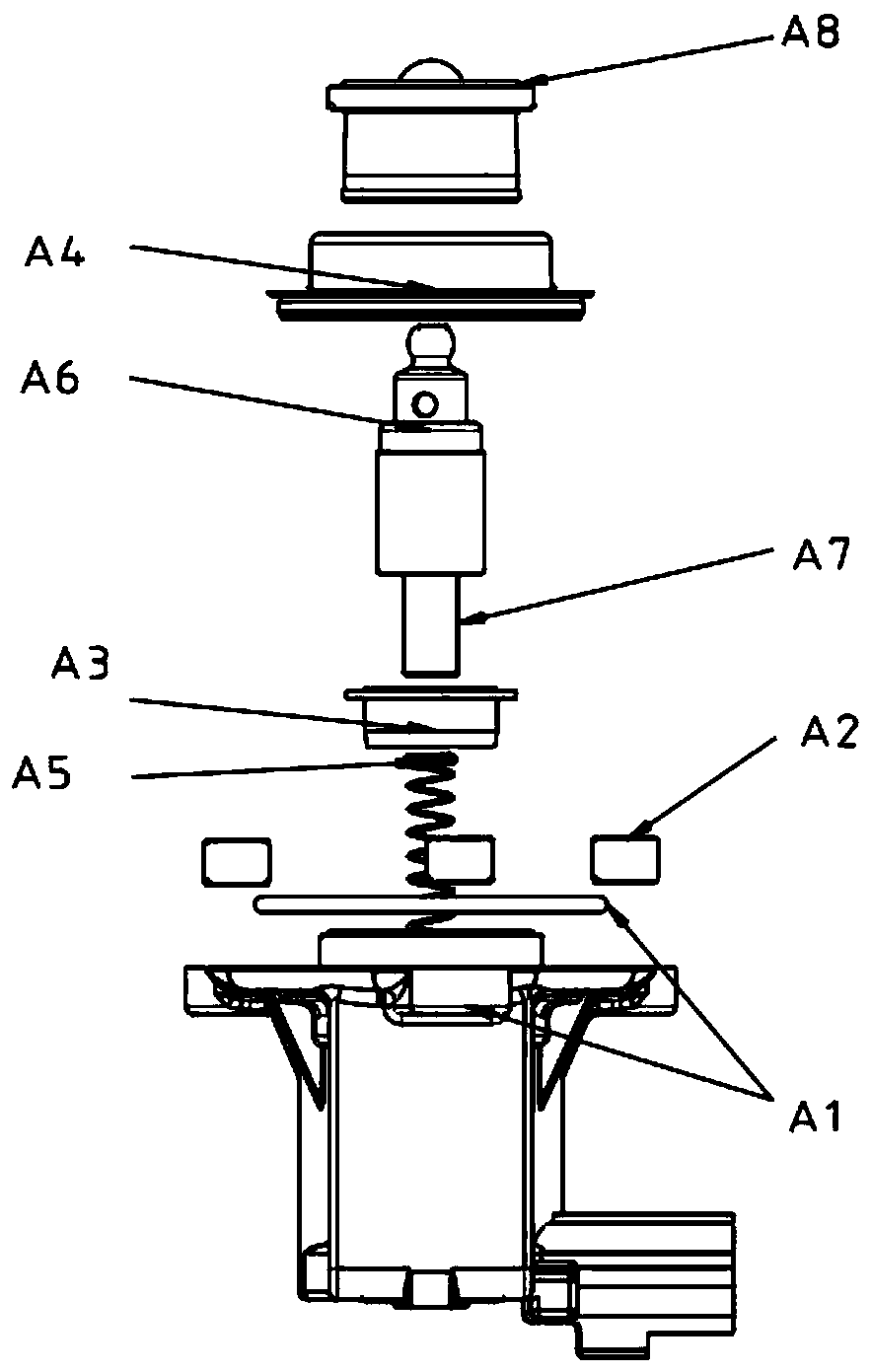
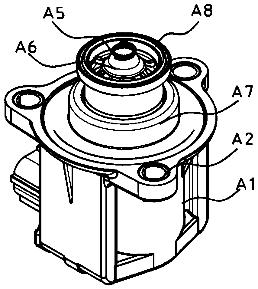
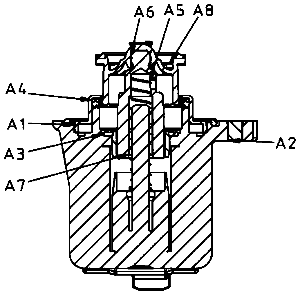
technical field [0001] The invention belongs to the technical field of automation equipment, in particular to an automation equipment suitable for assembling pressure relief valves. Background technique [0002] Turbine exhaust gas control regulating valve (hereinafter referred to as pressure relief valve) is an important part of automobile engine, such as Figure 1.1 to Figure 1.3 As shown, it is mainly composed of valve body (including O-ring) A1, bushing A2, fixed ring A3, side cap assembly A4, spring A5 and moving valve core assembly A10 (including moving valve core A6, shaft sleeve A7 and sealing body A8, such as Figure 1.4 and Figure 1.5 shown) composition. [0003] However, due to technical constraints, the current assembly of pressure relief valves is done manually. A production line of pressure relief valves requires at least 11 workers. The processing output depends on the proficiency of the employees, and they can only be operated by old employees. The speed ...

Claims


Application Information

Patent Timeline
Patent Type & Authority Patents(China)
IPC IPC(8): B23P21/00
CPCB23P21/006
Inventor 李齐俊
Owner UPTON AUTOMATION SYST KUNSHAN CO LTD
Learn More