Infrared communication decoding method of embedded system

An embedded system and infrared communication technology, which is applied in the field of infrared communication decoding, can solve problems such as excessive CPU time and long interrupt service time, and achieve the effect of improving high efficiency and stabilizing application effects

Active Publication Date: 2019-01-08
FUJIAN NORMAL UNIV +1
View PDF9 Cites 8 Cited by
  • Summary
  • Abstract
  • Description
  • Claims
  • Application Information

AI Technical Summary

Problems solved by technology

This method of determining the infrared boot code first and then starting the subsequent infrared waveform acquisition and data decoding has the disadvantages of long external interrupt service time and taking up too much CPU time.

Method used


Image

  • Infrared communication decoding method of embedded system
  • Infrared communication decoding method of embedded system
  • Infrared communication decoding method of embedded system

Examples


Embodiment Construction

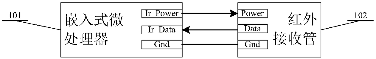
[0022] figure 1 Among them, 101 is an embedded microprocessor, and 202 is an infrared receiving tube, wherein, an output pin Ir_Power of 101 is connected with a Power pin of the infrared receiving tube (202), and an input pin Ir_Data of the embedded microprocessor (101) It is connected with the Data pin of the infrared receiving tube (202), and a pin Gnd of the embedded microprocessor (101) is connected with the Gnd pin of the infrared receiving tube (202).

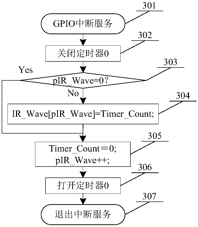
[0023] figure 2 201 marked in the block diagram is the 1-byte timer T0 interrupt count counter Timer_Count, 202 marked in the block diagram is the index number pIR_Wave of the 1-byte infrared signal waveform duration buffer area, and 203 marked in the block diagram is a 1-byte infrared signal The signal waveform acquisition completion flag IsIR_Wave, 204 is the n-byte infrared signal waveform duration buffer area IR_Wave.

[0024] In order to further illustrate the specific implementation of the present invention, in c...


PUM


Abstract

The invention relates to an infrared communication decoding method of an embedded system. The infrared communication decoding method consists of an integrated infrared receiving head and an embedded terminal which requires an infrared communication function. A microprocessor is provided with an infrared waveform data structure body which comprises a Timer_Count, a pIR_Wave, an IsIR_Wave, a cache regionIR_Wave and the like; an interrupt service and an application service are adopted to form a two-stage processing method; a timer 0 is started when in the interrupt service of a GPIO (General Purpose Input Output), and the application service is activated by conditions when in the interrupt service of the timer 0; a task of analyzing and decoding collected infrared waveform data is completed through the processing of the application service. The infrared communication decoding method has the beneficial effects that the acquisition, decoding and analysis of infrared waveforms are independently completed, so that the high efficiency of infrared decoding of the microprocessor is improved, and the universality of the microprocessor to different codes is also improved.

Description

technical field [0001] The invention relates to the field of wireless communication, in particular to an infrared communication decoding method of an embedded system. Background technique [0002] Infrared remote control has been widely used in household appliances and other fields. It uses infrared light with a wavelength of 0.76 μm to 1.5 μm as a control light source to transmit remote control instructions. Due to the strong directionality of infrared light communication, it is very suitable for short-distance wireless transmission. Infrared remote control is mainly composed of two parts: infrared transmitter and infrared receiver. Commonly used infrared remote control signal formats include: pulse position code (PPM code), pulse width code (PWM code) and Manchester code, etc. The difference is mainly in the width of the high and low levels of the pilot code representation, and the high and low voltage of logic 0 / 1. The flat width is different, and the number of bits enc...

Claims


Application Information

Patent Timeline
Patent Type & Authority Applications(China)
IPC IPC(8): G08C23/04H04B1/16H04B1/40
CPCG08C23/04H04B1/16H04B1/40
Inventor 吴允平钟炜楠李汪彪苏伟达王廷银潘明阳赵德鹏刘华松
Owner FUJIAN NORMAL UNIV
Why Eureka
Try Eureka