
An adjustable heat dissipation structure for a new energy vehicle battery

A new energy vehicle and heat dissipation structure technology, which is applied in the direction of batteries, secondary batteries, circuits, etc., can solve the problem that the heat dissipation structure cannot be adjusted, and achieve the effects of preventing hands-off, flexible use, and improving comfort

Active Publication Date: 2019-01-08
东莞市智嘉精密科技有限公司
View PDF8 Cites 18 Cited by
  • Summary
  • Abstract
  • Description
  • Claims
  • Application Information

AI Technical Summary

Problems solved by technology

[0006] The purpose of the present invention is to provide an adjustable heat dissipation structure for a new energy vehicle battery, which has the advantage of being able to adjust the cooling fan, and solves the problem that the traditional heat dissipation structure for new energy vehicles often cannot be adjusted. Through temperature detection, It can effectively dissipate heat when the battery is hot, and when the battery is not hot, there is no need to dissipate heat, avoiding unnecessary energy consumption

Method used


Image

  • An adjustable heat dissipation structure for a new energy vehicle battery
  • An adjustable heat dissipation structure for a new energy vehicle battery
  • An adjustable heat dissipation structure for a new energy vehicle battery

Examples


Embodiment Construction

[0022] The following will clearly and completely describe the technical solutions in the embodiments of the present invention with reference to the accompanying drawings in the embodiments of the present invention. Obviously, the described embodiments are only some, not all, embodiments of the present invention. Based on the embodiments of the present invention, all other embodiments obtained by persons of ordinary skill in the art without making creative efforts belong to the protection scope of the present invention.

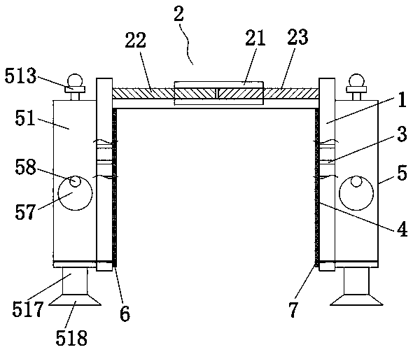
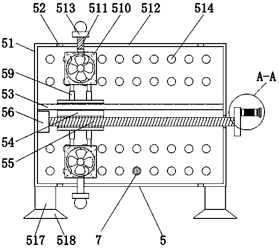
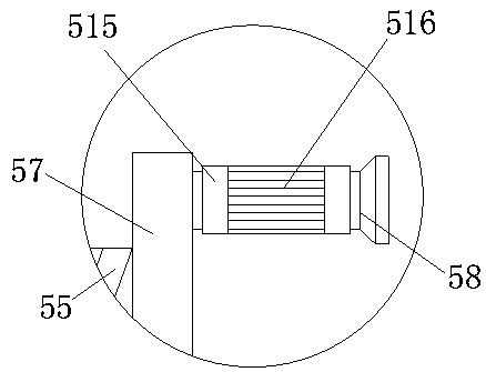
[0023] see Figure 1-4 , an adjustable heat dissipation structure for a new energy vehicle battery, comprising two heat dissipation plates 1, the top between the two heat dissipation plates 1 is fixedly connected by a connecting device 2, and the connecting device 2 includes an adjusting sleeve 21, a first connecting rod 22, The second connecting rod 23, the adjusting sleeve 21 is provided with threads to connect the first connecting rod 22 and the second conn...


PUM


Abstract

The invention discloses an adjustable heat dissipation structure for a new energy vehicle battery, includes two heat sink plates, The top between the two heat dissipation plates is fixedly connected by a connecting device, the surface of the heat dissipation plate is provided with a first heat dissipation hole, A dust-proof pad is fixedly connected to one side of the heat dissipation plate close to the connecting device, and a heat dissipation regulating device is fixedly connected to one side of the heat dissipation plate far away from the connecting device. The heat dissipation regulating device comprises a shell, wherein one side of the shell close to the heat dissipation plate is fixedly connected to the heat dissipation plate, and a visible glass window is fixedly connected to the groove at the top of the shell. As that heat dissipation regulate device is arranged, The invention solves the problem that the traditional heat dissipation structure of the new energy vehicle can not beadjusted, and can adjust the position of the heat dissipation fan according to the position of the heat dissipation hole of different types of the new energy battery, thereby achieving the effect ofmatching the heat dissipation area with the new energy battery, improving the use limit of the heat dissipation and realizing the flexible use.

Description

technical field [0001] The invention relates to the technical field of new energy vehicles, in particular to an adjustable heat dissipation structure for a new energy vehicle battery. Background technique [0002] The composition of new energy electric vehicles includes: electric drive and control systems, mechanical systems such as drive force transmission, and working devices for completing predetermined tasks. The most widely used power source is lead-acid battery, but with the development of electric vehicle technology, lead-acid battery is gradually replaced by other batteries due to its low energy, slow charging speed, and short life. The main power sources under development are sodium-sulfur batteries, The application of these new power sources, such as nickel-cadmium batteries, lithium batteries, and fuel cells, has opened up broad prospects for the development of electric vehicles. The traditional heat dissipation structure for new energy vehicles often cannot be ad...

Claims


Application Information

Patent Timeline
Patent Type & Authority Applications(China)
IPC IPC(8): H01M10/613H01M10/625H01M10/635H01M10/6554H01M10/6556H01M10/6563
CPCH01M2220/20H01M10/613H01M10/625H01M10/635H01M10/6554H01M10/6556H01M10/6563Y02E60/10
Inventor 王大幸
Owner 东莞市智嘉精密科技有限公司
Learn More