A quick changing device for a surgical instrument

A technology of surgical instruments and control devices, applied in the field of medical instruments, can solve the problems of cumbersome locking operation process, inconvenient surgical operation, and difficult implementation

Active Publication Date: 2019-01-11
SHANGHAI MICROPORT MEDBOT (GRP) CO LTD
View PDF14 Cites 19 Cited by
  • Summary
  • Abstract
  • Description
  • Claims
  • Application Information

AI Technical Summary

Problems solved by technology

[0005] For example, the Chinese patent application CN106344161A discloses a quick-change mechanism for the terminal tool of a minimally invasive spinal surgery robot, which can realize the rapid installation and disassembly of the terminal instrument during the operation. However, the locking operation process is cumbersome and difficult for medical staff to implement quick operation
Another Chinese patent application CN106102642A discloses a technology and method of a shell surgical sleeve installation part, which can realize the installation and disassembly of the surgical sleeve during the operation, but its structural design makes it necessary to operate the unlock button to realize the surgical sleeve. In addition, the technical structure disclosed in this patent requires a large space to realize the layout of the mechanism, which makes it difficult to implement the compact design of the entire structure.

Method used


Image

  • A quick changing device for a surgical instrument
  • A quick changing device for a surgical instrument
  • A quick changing device for a surgical instrument

Examples


Embodiment 1

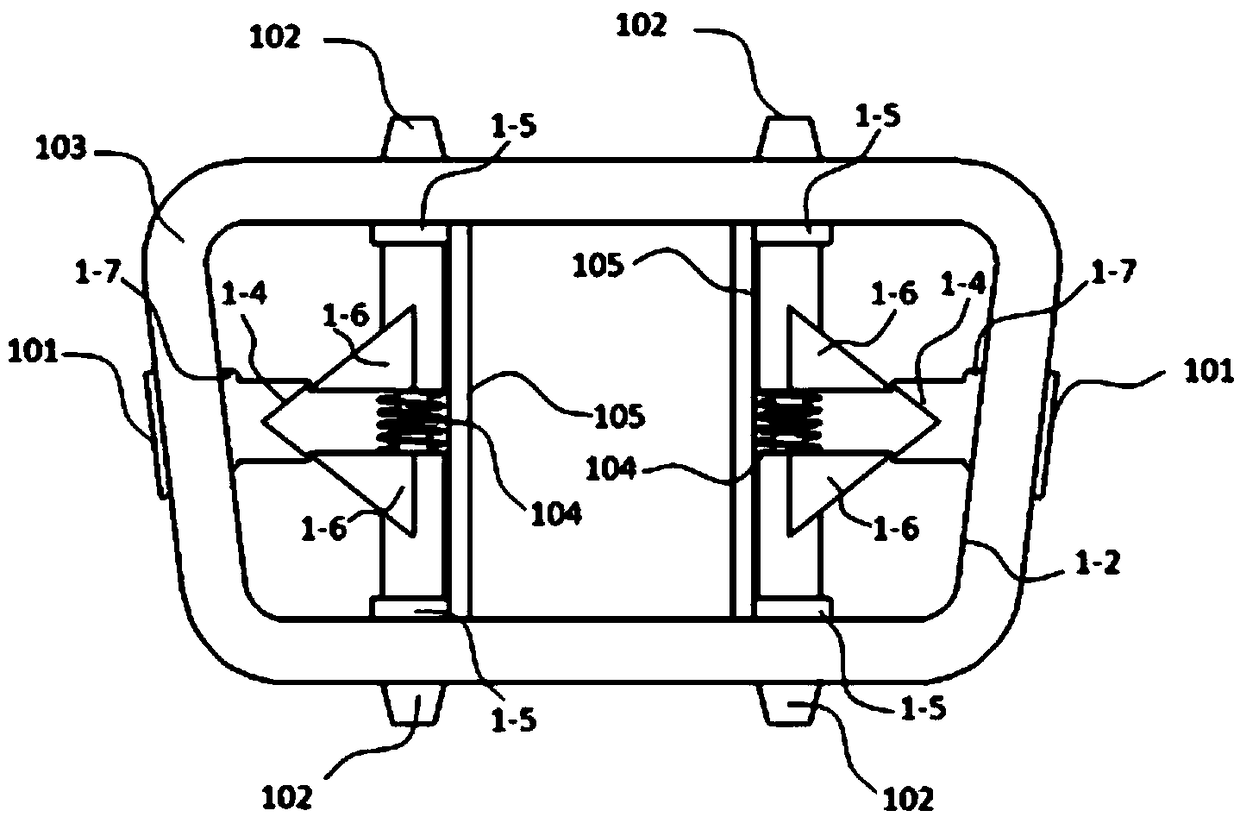
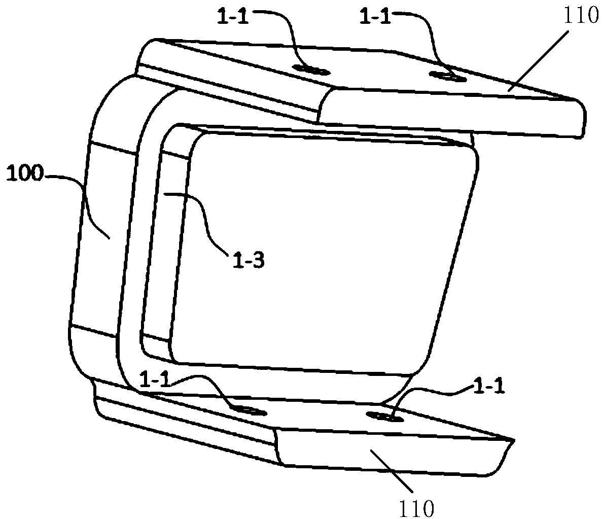
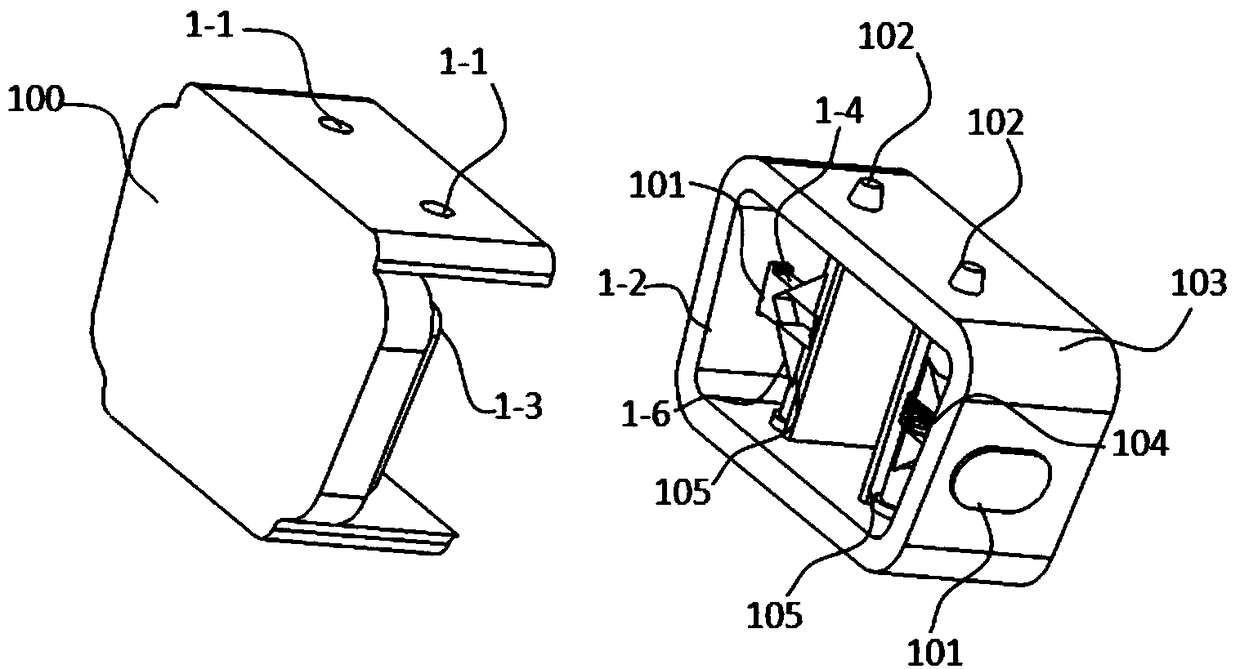
[0137] Please refer to Figure 1 to Figure 7 , figure 1 It is a structural schematic diagram of the installation base and its upper locking mechanism provided by Embodiment 1 of the present invention, figure 2 It is a schematic structural diagram of the installation joint provided by Embodiment 1 of the present invention, image 3 It is a schematic diagram of the state where the installation base and the installation joint are separated from each other provided by Embodiment 1 of the present invention, Figure 4 It is a schematic diagram of the mutual fixing state of the installation base and the installation joint provided by Embodiment 1 of the present invention, Figure 5 It is a schematic diagram of the use state of the installation base and its upper locking mechanism provided by Embodiment 1 of the present invention, Image 6 It is a schematic structural diagram of the locking pin provided in Embodiment 1 of the present invention, Figure 7 It is a structural schema...

Embodiment 2

[0155] Please refer to Figure 8 to Figure 15 , Figure 8 It is a schematic diagram of the state where the installation joint and the installation base are separated from each other provided by the second embodiment of the present invention, Figure 9 It is a schematic cross-sectional view of the separation of the installation base and the installation joint provided by the second embodiment of the present invention, Figure 10 It is a schematic diagram of the assembly and connection process of the installation base and the installation joint provided by the second embodiment of the present invention, Figure 11 It is a schematic diagram of the mutual locking state of the installation base and the installation joint provided by the second embodiment of the present invention, Figure 12 It is a schematic diagram of the appearance state of the mutual locking of the installation base and the installation joint provided by the second embodiment of the present invention, Figure...

Embodiment 3

[0173] Please refer to Figure 16 to Figure 19 , Figure 16 It is a structural schematic diagram of the installation base and its upper locking mechanism provided by the third embodiment of the present invention, Figure 17 It is a schematic structural diagram of the installation joint provided by Embodiment 3 of the present invention, Figure 18 It is a schematic diagram of the state where the installation base and the installation joint are separated from each other provided by the third embodiment of the present invention, Figure 19 It is a schematic diagram of a state in which the installation base and the installation joint are fixed to each other provided by the third embodiment of the present invention.

[0174] Such as Figure 16 to Figure 19 As shown, the quick change device includes a mounting base 202, a mounting joint 201, a positioning mechanism and a locking mechanism. The installation joint 201 is inserted on the installation base 202 and the two are positi...


PUM


Abstract

The invention relates to a quick changing device for a surgical instrument, which realizes quick connection and disassembly between the surgical instrument and the end of a robot arm. The quick changing device comprises a mounting base, a mounting joint, a positioning mechanism and a locking mechanism. The positioning mechanism comprises a first positioning part and a second positioning part matching the same, wherein the first positioning part and the second positioning part are respectively arranged on the mounting base and the mounting joint; the locking mechanism includes a first connectordisposed on the mounting joint, and a control device and a second connector disposed on the mounting base. The control device is configured to control the second connector to be locked with the firstconnector so that the first positioning portion and the second positioning portion remain in mating contact, thereby realizing the assembly between the mounting joint and the mounting base. The control device is further configured to control the second connection member and the first connection member to be unlocked so that the first positioning portion and the second positioning portion are in adetachable state, thereby realizing unloading between the mounting joint and the mounting base.

Description

technical field [0001] The invention relates to the technical field of medical instruments, and particularly designs a quick-change device for surgical instruments. Background technique [0002] With the continuous development of robot technology, minimally invasive surgery is gradually entering the public's field of vision in a form different from the traditional one. The precise and efficient surgical implementation process is reflected in all aspects of medical treatment, and the medical treatment environment of patients has also been improved. It has been greatly improved, and the level of modern medical technology has also moved towards a new level. Research on related fields of minimally invasive surgery combined with robotic technology is also an important part of the development of modern medicine. [0003] Minimally invasive surgery is currently the most commonly used method of minimally invasive surgery. Research on its combined application with robotic technology...

Claims


Application Information

Patent Timeline
Patent Type & Authority Applications(China)
IPC IPC(8): A61B34/30A61B17/00
CPCA61B17/00234A61B34/30A61B34/73
Inventor 袁帅何超戴根喜
Owner SHANGHAI MICROPORT MEDBOT (GRP) CO LTD
Why Eureka
Try Eureka