Pressure swing adsorption device based on thermodynamic model
A thermodynamic model, pressure swing adsorption technology, applied in the direction of inorganic chemistry, chemical instruments and methods, oxygen/ozone/oxide/hydroxide, etc., can solve the problem of reducing the adsorption capacity of zeolite molecular sieves, insufficient adsorption of zeolite molecular sieves, and intermediate areas Solve the problems of slow adsorption and other problems, and achieve the effect of simple structure, reasonable design and increased adsorption capacity
- Summary
- Abstract
- Description
- Claims
- Application Information
AI Technical Summary
Problems solved by technology
Method used
Image
Examples
Embodiment 1
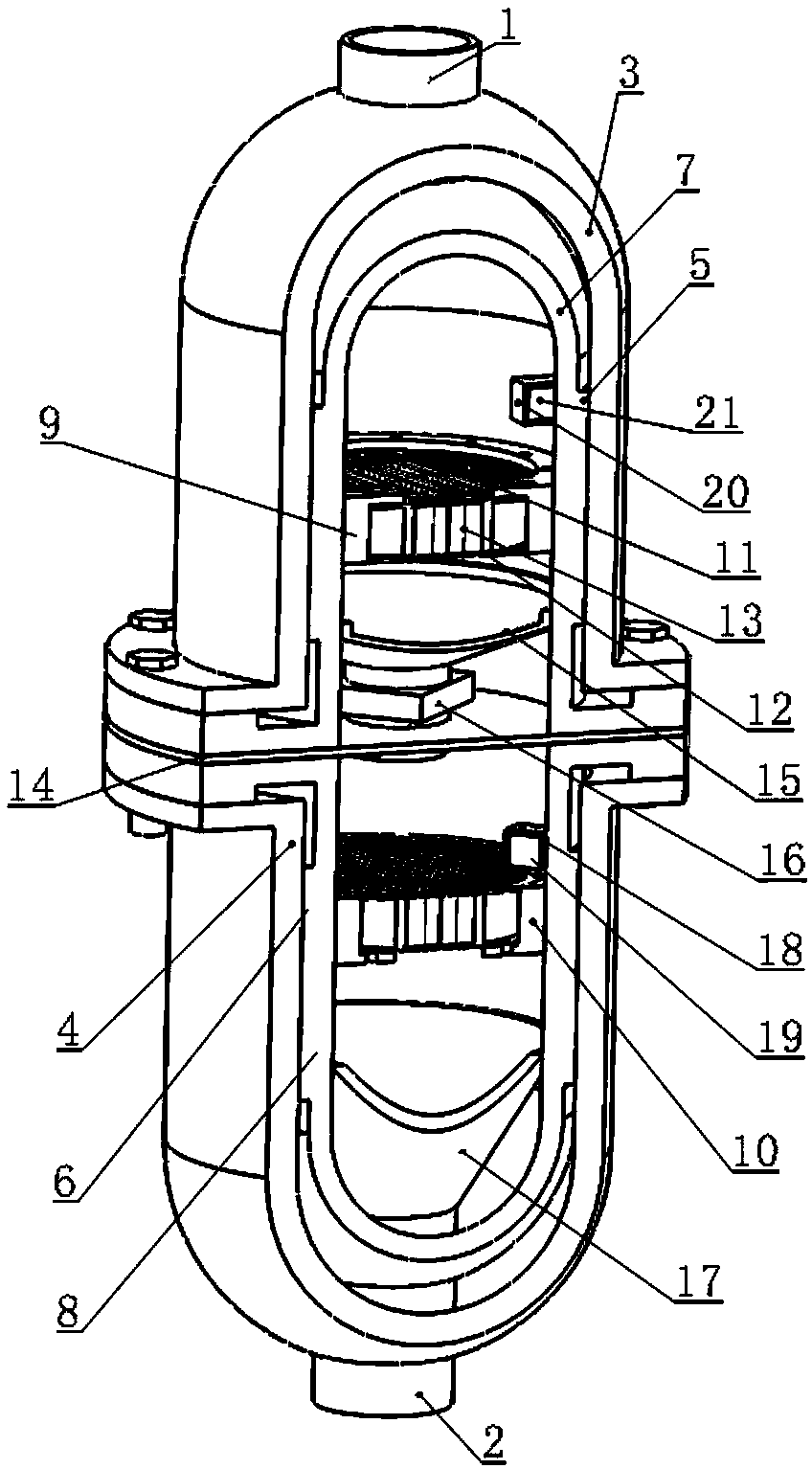
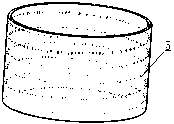
[0015] Such as figure 1 , figure 2 As shown, a pressure swing adsorption device based on a thermodynamic model according to the present invention includes an air outlet pipe 1, an air inlet pipe 2, an upper cover body 3, a lower cover body 4, a cold air pipe I5, a cold air pipe II6, and an upper shell 7 , lower shell 8, annular groove Ⅰ9, annular groove Ⅱ10, steel wire mesh Ⅰ11, steel mesh Ⅱ12, molecular sieve 13, partition 14, shunt cover Ⅰ15, single solenoid valve 16, shunt cover Ⅱ17, bracket Ⅰ18, temperature sensor Ⅰ19 , bracket II20, temperature sensor II21, wherein the upper housing 7 is installed inside the upper housing 3, the lower housing 8 is installed inside the lower housing 4, the cold air pipe I5 is located between the upper housing 3 and the upper housing 7, and the cooling The trachea II6 is located between the lower cover body 4 and the lower housing 8, the annular groove I9 is located inside the upper housing 7, the bracket II20 is located inside the up...
Embodiment 2
[0017] Such as figure 1 , figure 2 As shown, a pressure swing adsorption device based on a thermodynamic model according to the present invention includes an air outlet pipe 1, an air inlet pipe 2, an upper cover body 3, a lower cover body 4, a cold air pipe I5, a cold air pipe II6, and an upper shell 7 , lower shell 8, annular groove Ⅰ9, annular groove Ⅱ10, steel wire mesh Ⅰ11, steel mesh Ⅱ12, molecular sieve 13, partition 14, shunt cover Ⅰ15, single solenoid valve 16, shunt cover Ⅱ17, bracket Ⅰ18, temperature sensor Ⅰ19 , bracket II20, temperature sensor II21, wherein the upper housing 7 is installed inside the upper housing 3, the lower housing 8 is installed inside the lower housing 4, the cold air pipe I5 is located between the upper housing 3 and the upper housing 7, and the cooling The trachea II6 is located between the lower cover body 4 and the lower housing 8, the annular groove I9 is located inside the upper housing 7, the bracket II20 is located inside the up...
Embodiment 3
[0019] Such as figure 1 , figure 2 As shown, a pressure swing adsorption device based on a thermodynamic model according to the present invention includes an air outlet pipe 1, an air inlet pipe 2, an upper cover body 3, a lower cover body 4, a cold air pipe I5, a cold air pipe II6, and an upper shell 7 , lower shell 8, annular groove Ⅰ9, annular groove Ⅱ10, steel wire mesh Ⅰ11, steel mesh Ⅱ12, molecular sieve 13, partition 14, shunt cover Ⅰ15, single solenoid valve 16, shunt cover Ⅱ17, bracket Ⅰ18, temperature sensor Ⅰ19 , bracket II20, temperature sensor II21, wherein the upper housing 7 is installed inside the upper housing 3, the lower housing 8 is installed inside the lower housing 4, the cold air pipe I5 is located between the upper housing 3 and the upper housing 7, and the cooling The trachea II6 is located between the lower cover body 4 and the lower housing 8, the annular groove I9 is located inside the upper housing 7, the bracket II20 is located inside the up...
PUM
 Abstract
Description
Claims
Application Information
 - R&D Engineer
- R&D Manager
- IP Professional
- Industry Leading Data Capabilities
- Powerful AI technology
- Patent DNA Extraction
Browse by: Latest US Patents, China's latest patents, Technical Efficacy Thesaurus, Application Domain, Technology Topic, Popular Technical Reports.
© 2024 PatSnap. All rights reserved.Legal|Privacy policy|Modern Slavery Act Transparency Statement|Sitemap|About US| Contact US: help@patsnap.com


