
Ultrasonic welding base structure

A technology of ultrasonic welding and bottom table, applied in welding equipment, non-electric welding equipment, metal processing equipment and other directions, can solve the problems of increasing manufacturing cost, improve the speed of mold change, improve welding quality, regular and beautiful solder joints. Effect

Pending Publication Date: 2019-01-11
WUHU XINBAO ULTRASONIC EQUIP
View PDF0 Cites 0 Cited by
  • Summary
  • Abstract
  • Description
  • Claims
  • Application Information

AI Technical Summary

Problems solved by technology

In the welding of processing a set of kits, it is often necessary to prepare a set of welding equipment for welding, which causes an increase in manufacturing costs.

Method used


Image

  • Ultrasonic welding base structure

Examples


Embodiment 1

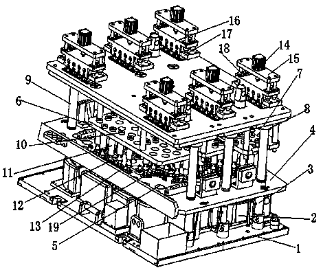
[0012] Example 1, such as figure 1 As shown, an ultrasonic welding bottom platform structure, the ultrasonic welding bottom platform structure includes a bottom plate 1, a bottom support block group 2 arranged on the bottom plate 1, and a synchronous connecting rod arranged at the four corners on the top of the bottom connecting plate Group 3, through the membrane plate structure connected to the synchronous connecting rod group and the upper guide plate structure arranged on the upper part of the membrane plate structure and connected with the synchronous connecting rod group 3, the membrane plate structure includes the membrane connecting plate 4. The guide hole 5 provided on the membrane connection plate, the upper guide plate structure includes an upper guide plate body 6 and multiple sets of upper locking block structures arranged on the upper guide plate body.

[0013] It is characterized in that: the lower part of the upper guide plate structure is movably provided with...


PUM


Abstract

The invention provides an ultrasonic welding base structure. The ultrasonic welding base structure comprises a bottom plate, a bottom support block set arranged on the bottom plate, synchronous connecting rod sets connected with four corners of the upper portion of the bottom plate, a membrane plate structure penetrating through the synchronous connecting rod sets, and an upper guide plate structure arranged on the upper portion of the membrane plate structure and connected with the synchronous connecting rod sets, wherein the membrane plate structure includes a membrane connection plate and guide holes formed in the membrane connection plate. The ultrasonic welding base structure is characterized in that the lower portion of the upper guide plate is movably provided with a welding connection pedestal; and the welding connection pedestal comprises edge locking blocks arranged at the lower portion of the upper guide plate structure, connection lock sleeves arranged on the edge locking blocks, locking rods, a welding tool connection table and a welding tool connection block set. By adoption of the movable arrangement of the welding connection pedestal, the speed of changing a membrane and the welding quality are improved.

Description

technical field [0001] The invention relates to an ultrasonic welding auxiliary part, in particular to an ultrasonic welding base structure. Background technique [0002] At present, the existing ultrasonic welding platform is used for spot welding of workpieces and welded components for welding workpieces. However, a set of welding equipment is often prepared for welding in the process of processing a set of kits, which increases the manufacturing cost. Contents of the invention [0003] The object of the present invention is to provide an ultrasonic welding platform structure, which solves the problem of the ultrasonic welding platform structure for the fast replacement of welding tool assemblies for a set of sets (left and right). [0004] The technical solution adopted by the present invention to solve the technical problem is: an ultrasonic welding base structure, the ultrasonic welding base structure includes a base plate, a bottom supporting block group arranged on...

Claims


Application Information

Patent Timeline
Patent Type & Authority Applications(China)
IPC IPC(8): B23K20/26B23K20/10
CPCB23K20/10B23K20/26
Inventor 潘保平
Owner WUHU XINBAO ULTRASONIC EQUIP
Learn More