An automatic assembly method for a handle lock

An automatic assembly and handle lock technology, applied in assembly machines, metal processing equipment, manufacturing tools, etc., can solve problems such as insufficient handle lock assembly, reduced production profits of enterprises, and handle lock assembly failures, reducing human effort. The influence of factors, the reduction of assembly costs, the effect of high degree of automation

Active Publication Date: 2020-09-15
浙江理工大学瓯海研究院有限公司 +1
View PDF7 Cites 0 Cited by
  • Summary
  • Abstract
  • Description
  • Claims
  • Application Information

AI Technical Summary

Problems solved by technology

[0003] In the prior art, when the above-mentioned handle lock is assembled, it is generally assembled manually. First, the handle 41 sleeved with the sleeve 42 is inserted into the shaft hole 431 of the panel 43, and the hook 441 of the torsion spring 44 is inserted into the shaft hole 431 of the panel 43. Hanging on the boss 432, the free end 442 of the torsion spring 44 is limited in the corresponding second guide groove 4111, and then the handle 41 is rotated 90 degrees, and the rotating retaining ring 45 and the spacer are sequentially set on the rotating shaft 46 and the axial retaining ring 47, wherein the two protrusions 451 of the rotating retaining ring 45 are limited in the corresponding second guide groove 4111 to realize the installation of the handle lock. Manual assembly is not only low in production efficiency, but also requires a lot of labor. Manpower and material resources, and when assembling, one hand rotates the handle to 90 degrees, and the other hand strictly snaps the protrusion 451 of the rotating retaining ring 45 into the second guide groove 4111 of the rotating shaft 411, thereby realizing the handle The assembly of the lock, but in the actual assembly process, due to the instability of human factors, it is inevitable that the deviation problem between the above-mentioned protrusion 451 and the second guide groove 4111 is caused by manual assembly, so that the handle The lock is not assembled properly, and even the handle lock assembly fails, which greatly reduces the production efficiency; at the same time, it is laborious to manually rotate the handle 90 degrees for assembly, which increases labor costs, reduces production efficiency, and reduces production efficiency. production profit of the enterprise

Method used


Image

  • An automatic assembly method for a handle lock
  • An automatic assembly method for a handle lock
  • An automatic assembly method for a handle lock

Examples


Embodiment Construction

[0050] The present invention will be further described in detail below in conjunction with the accompanying drawings and embodiments.

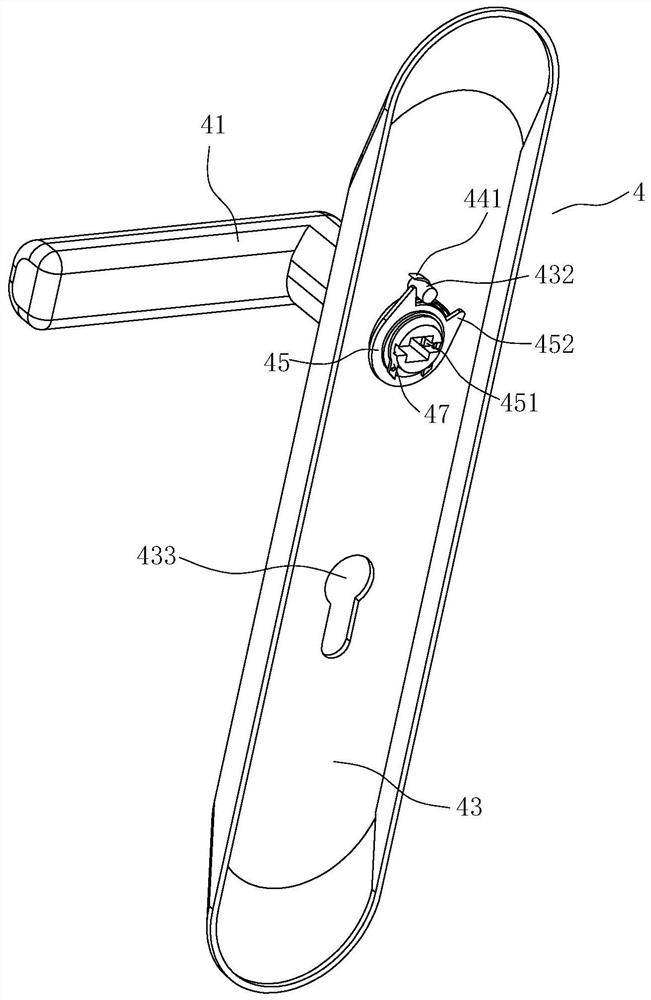
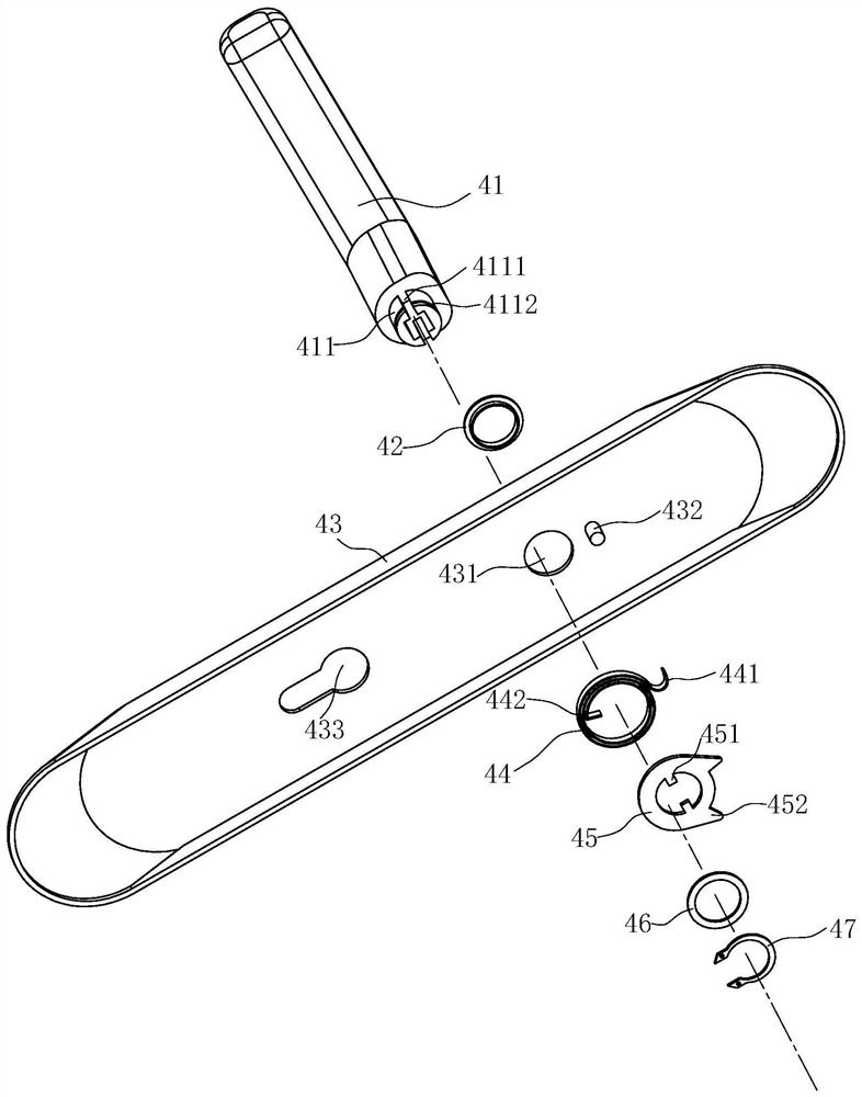
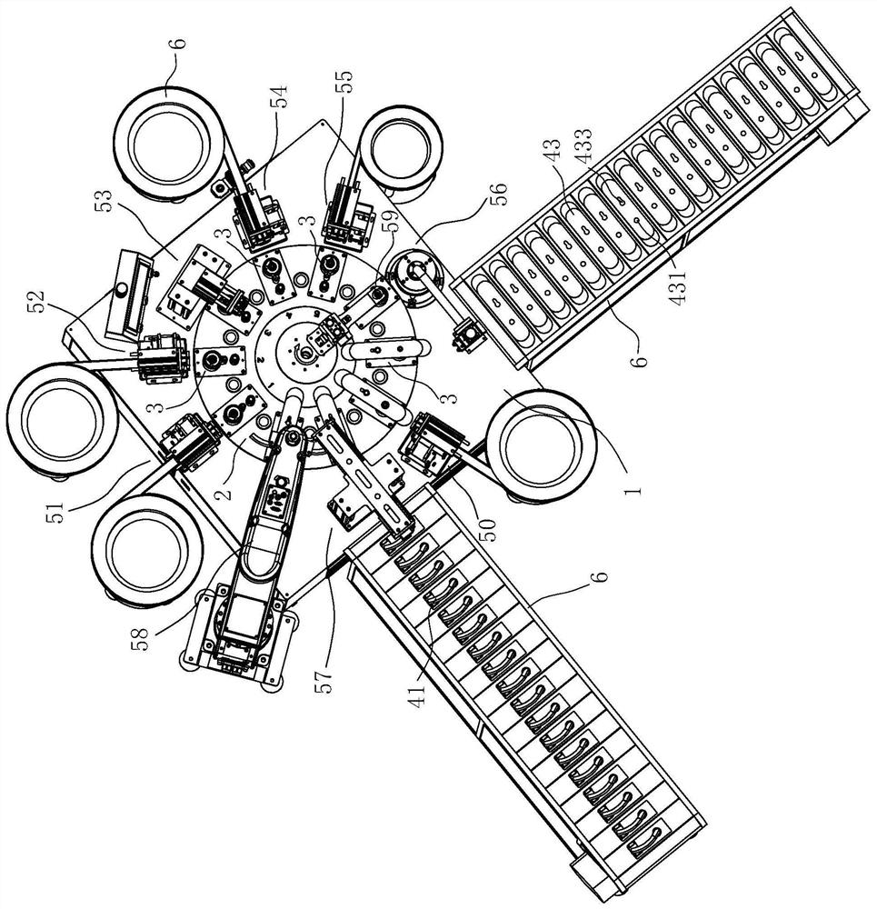
[0051] Such as Figure 3 to Figure 21 As shown, the automatic assembly equipment for the handle lock according to the embodiment of the present invention includes an assembly platform 1 and a turntable 2 which is arranged on the assembly platform 1 and can rotate horizontally relative to the assembly platform 1, wherein,

[0052] Such as image 3 and Figure 4 As shown, on the assembly platform 1 adjacent to the edge of the turntable 2 and in accordance with the rotation direction of the turntable 2, a plurality of working mechanisms are arranged in sequence, and each working mechanism is correspondingly provided with a feeding mechanism 6, and each working mechanism is respectively axial Retaining ring removing mechanism 51, gasket removing mechanism 52, rotating mandrel removing mechanism 53, rotating retaining ring removing mechanism 54, ...


PUM


Abstract

The invention relates to an automatic assembly method of a handle lock. The handle lock is assembled through handle lock automatic assembly equipment. The handle lock automatic assembly equipment comprises a controller and an assembly platform; a rotary plate is arranged on the assembly platform; a plurality of working mechanisms are sequentially arranged at the positions, close to the edge, of the rotary plate in the rotating direction of the rotary plate; a feeding mechanism is arranged on each working mechanism correspondingly; and the multiple working mechanisms and the rotary plate collect working data and feed the working data back to the controller, and complete action control is conducted through the controller. At present, manual assembly is adopted, and no relevant automatic assembly equipment exists on the market; handle lock automatic assembly equipment developed by the project fills the gap in the market; and the automation degree is high. Through the automatic assembly method, the whole handle lock is conveniently assembled, the assembly efficiency is greatly improved, due to the fact that the whole process is automatically controlled and operated through a master control program, the influence of human factors are reduced, and the profits of enterprises are increased

Description

technical field [0001] The invention belongs to the technical field of automatic assembly, and in particular relates to an automatic assembly method for a handle lock. Background technique [0002] The door handle lock is an object installed on the door to facilitate opening and closing the door by hand. There are many kinds of door handle locks for the door on the market. figure 1 A handle lock structure is given. The handle lock structure includes a handle 41, a shaft sleeve 42, a panel 43, a torsion spring 44, a rotating retaining ring 45, a gasket 46 and an axial retaining ring 47. The panel 43 is provided with A shaft hole 431, one end of the handle 41 has a rotating shaft 411, and the outer peripheral wall of the rotating shaft 411 is provided with at least two second guide grooves 4111 penetrating up and down. In the shaft hole 431, the rotating shaft 411 passing through the shaft hole 431 is sleeved with a torsion spring 44, a rotation retaining ring 45, a gasket 46...

Claims


Application Information

Patent Timeline
Patent Type & Authority Patents(China)
IPC IPC(8): B23P21/00
CPCB23P21/00
Inventor 周哲炜李红军陈孝荣
Owner 浙江理工大学瓯海研究院有限公司
Why Eureka
Try Eureka